4.10. Design of the chamfers stems and rasps
4.10.1. Summary
With an aim of respecting rigorously the principles of Geometric Anchoring in the design of stems SL Plus, the chamfers along the 4 rectangular edges of the anchoring zone were mathematically defined.
In the AlloClassic stems, the round-offs along the 4 rectilinear edges had constant radius all along the edges and unique for all the sizes, and the corner of the teeth of the AlloClassic rasps was more or less pointed and in any case nondefined by the Originator.
By preoccupation with an improvement, I considered that the chamfers of stems SL Plus were to respect the conical geometry of anchoring and to vary regularly, in width, along each edge, and for all the sizes of the series.
For SL Plus rasps, that I calculated and transmitted to the production to the nearest micron, especially for the corner of the teeth, I introduced a width difference between the chamfer of the stem and the chamfer of the rasp on the corresponding level such as it is not the chamfer of the stem which rests everywhere at the bottom of the chamfer prepared by the rasp in the osseous bed, but that the primary pressure is exerted primarily on the edges of the rectangular faces of the stem.
The primary contact surface of the implant with the rectified osseous bed is increased compared to the stems with not chamfered edges.
Small space left empty between the chamfer of the prepared bone and the chamfer of the implant, plays the part of a reserve of radial impaction. Incidentally, space between the chamfers absorbs some chips left by the rasping.
4.10.2. Relations between the chamfers of the rasp and the chamfers of the stem in stems SL Plus.
In the cortical preparation of the femur, the dimensions of the chamfers to the four edges of the prosthetic stem have an particular importance. The technology of obtaining the chamfers is detailed lower.
La osseous preparation with the rasps of stems SL Plus present one chamfer slightly less broad than the chamfer of the corresponding stem so that the oblique surface to 45 degrees of the chamfer of the stem does not come in mechanical contact under pressure with the chamfer prepared in the bone with the rasp.
I find preferable that the osseous support occurs only on the immediate edges of the stem on both sides of the chamfer i.e. about 1 to 3 mm all along the chamfer and certainly not on the face of the chamfer. (drawing to make AD)
Of this fact the stem of ZM is narrowly tight on the cortical bone along 8 longitudinal bands, each chamfer having two contact lines.
It is thanks to the support along the 8 bands of contact that one can approach as well as possible a radial distribution of the constraints which leave the stem towards the bone in 8 peripheral directions of a section of the stem.
Also, the 8 longitudinal bands make it possible to minimize in a very effective way the early descent of the stem in the diaphysis after a correct placement as indicated in the chapter of the theory of the Field of Bone Vitality.
4.10.3. Limitation of sinking by calculated rasps
Indeed, immediately after an implantation even satisfactory and felt manually by the operator as closely related to the osseous bed, the surface which is strictly in contact with the bone is not very wide yet and of this fact only a small fraction of surface the bone receives important constraints.
These constraints transitorily excessive involve in the days which follow a light resorption of the bone and possibly a light descent from 1 to 2 mm of the stem in the bone until, because of small resorption, the surface of contact between the prosthesis and the bone is widened. The contact surface is so that the junction between the prosthesis and the bone is in the Field of Bone Vitality where the implant is in stationary cohabitation with the bone, which will not resorb any more.
4.10.4. The osseointegration is optional.
I make a point of recalling that the geometrical fixing of a prosthesis calculated by applying my processes, does not require imperatively the help of the osteointegration. This one is a very useful thing, very important, but that I do not consider essential.
What I have just said is one of the factors of great success of my prostheses with Geometrical Anchoring because bone regrowth does not occur automatically in all patients. For example, the too old patients, whose metabolic functions, because of a restricted activity and whose medullary canals tend to widen, can not react positively to the presence of an implant.
Certain reoperated patients whose cemented prosthesis was extracted and whose internal surface of the diaphysis was inhibited by the toxic components of cement which remain on the spot after reoperations, or for any other biological reason, present also a defective osteointegration. Among these patients, the aptitude for bone regrowth inside the medullary canal is bad and it is necessary that the stems also hold at these people.
If it needed absolutely bone regrowth, this prosthesis would have good success only among relatively young patients.
4.10.5. Chamfer analysis
I am of opinion to avoid the direct contact of the chamfer of the stem against the chamfer of the prepared osseous bed, because of the absolutely inevitable presence of remains and chips due to the preparation by the rasp which carves a structure in staircase on the level of each tooth. This structure is left by the last movements of rasping, each stroke of the rasp always ending in a blocking and never leaving a smooth and “planed” surface. It is in no case an ideal groove obtained by milling in workshop.
At this place, the geometrical quality of this surface is precise only with one or two tenth of mm approximately. While scraping with a pin in the corners of the prepared bone, the operator can easily hear the noise of this structure in stairs.
Some residual debris, and of the chips which were not detached from the bone, find their place in the small interval left between the chamfer of the bone and the chamfer of the stem thanks to the difference of the chamfers of the rasp and the stem.
One can evaluate with approximately 9 cases out of 10 the situation where the stem, once impacted in the osseous bed prepared according to my method, will not go down absolutely any more and in a few weeks, the osteointegration coming to help final fixing.
For the few too old patients or whose interior surface of the femur was biologically damaged by cement which remained years in place or for very old patients whose osseous vitality became negligible, the stems designed with Geometrical Anchoring in this way offer a final stability after a maximum of descent of 2 mm and, because of the intimate contact between the cortical bone and 8 peripheral surfaces of the stem, surface is such as the bone will not resorb more and that the prosthesis will not sink any more. This type of prosthesis does absolutely not need the osteointegration.
4.10.6. Geometrical structure of the chamfers of the stem.
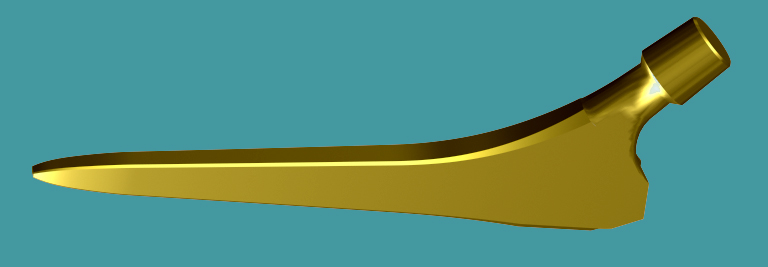
The chamfers present on the stems have an uninterrupted variable width and this width regularly widens from the tip of the stem until the proximale part of the stem. This property is essential to satisfy my principles of Geometrical Anchoring, and so that the stem behaves in the least detail in its osseous sleeve like a conical junction.
The widening of the chamfer is everywhere proportional to the antero-posterior thickness of the stem. Chamfers of this type could not have been established in a simple way with a design software 3D of the trade, which cannot apply, other that chamfers of constant width on a given metal part.
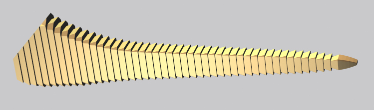
As we can see it in addition, the rectangular principal shape of the stem before the application of the calculation algorithm of the chamfers is obtained by a cutting in 100 levels in the direction length.
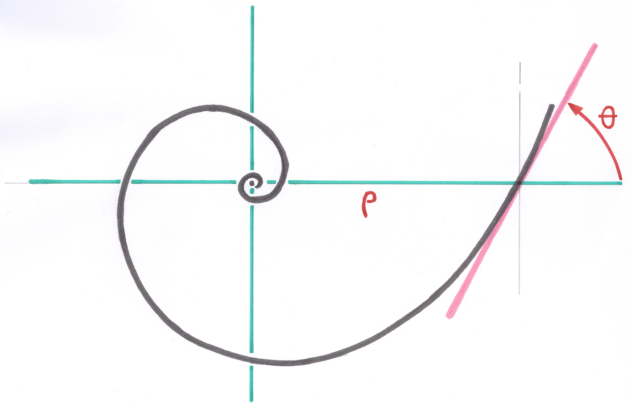
This cutting is equidistant for the rectilinear SL Plus stems, but for the curved stems of the following generations like Modular-Plus the cutting is logarithmic on a curvilinear axis in logarithmic spiral.
On each section perpendicular to the axis, corresponding to each level of cutting, the chamfer is calculated in a not orthonormed local vector space, while defining, on the one hand the angle of the chamfer, for example 45 degrees, and on the other hand the side of the chamfer as a percentage the thickness of the stem on this level.
This percentage is given by the corresponding data of the Parameter Base of the system. This value is the same one for all the sizes of the series, but is automatically adapted to each size by the system of the Growing Factors.
The width of the chamfer is thus recomputed independently on each level, all along the stem and for all the stems of the series.
To satisfy the principle of Ascending Interlocking, see theory chapter 4.7.2., If one takes two consecutive sizes of stems of the series, the widths of the chamfers measured on each of the two stems at the place where their sections have the same thickness and the same width, the width of the chamfers is identical. This way, two stems of successive size can be implanted in the bone prepared with the same rasp.
It should be remembered that the chamfer remains relatively small and cannot have any influence on the rotary stability of the rod once installed.
In any case, the orientation of the rasp when placing the very first small rasp or the first rasp which begins to have contact with the cortical bone must be perfectly monitored because, with rasps impacted so coaxial, the anteversion orientation is preserved from the first rasp which has made its way.
----