5.3.3. Inlays Bicon Antiluxation
5.3.3.1. Intraoperative design of Antiluxation inserts
The idea of a cup which reduces the risk of dislocation compared to the flat cup appeared during an operation on a young patient at the Necker Hospital with Professor and friend Philippe Touzet, whom I assisted in all his interventions with my implants, to help him resolve always exceptional cases and to enrich my experience.
When placing an insert in a Zweymüller Titanium shell in 1987, it appeared during the stability test of the femoral head that the lifting of the head was occurring a little too easily. However, when observing the head in place in the insert, it was not possible to notice any defect. The positioning of the stem and its antetorsion were not open to criticism either and therefore we thought about finding the reason for this dislocation.
It is well known that bony overhangs on the edge of the acetabulum could cause leverage on the femur bone or metal neck, but this was not the reason.
So I suggested manually searching for the conflicting area below the head. Unexpectedly, it was not a lack of coverage of the acetabulum on the side where the head protruded from the hemisphere of the acetabulum but a lever arm effect between the metal neck of the stem and the non-visible edge of the polyethylene hemisphere. It should be noted that at the time, the diameter of the metal neck of Zweymüller's Alloclassic stem was 16 millimeters, and therefore a somewhat excessive diameter. I was able to correct this defect a few years later on the necks of the Zweymüller SL Plus stems.
Following the observation made that day, having tactilely detected the location of the conflict with the cervix, I asked for Professor Touzet's agreement to recut, with a fine-blade scalpel, the polyethylene to go down below the level of the plane of the acetabulum and remove a crescent moon shape so that the height of the border is below the level of the plane.
From the next stability test, it appeared that the problem had been corrected and that it was no longer possible to dislocate the head in this direction. Stability has returned to normal and acceptable.
5.3.3.2. Geometric then computer concretization
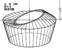
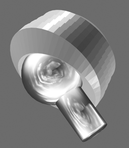
After the development of the second version of the prosthesis creation software in 1988, it was possible for me to represent the ideal shape of an inclined insert which, instead of just presenting an elevation on the side where the dislocation occurs as with all American manufacturers of the time without exception, there was simultaneously raising of one side and lowering of the diametrically opposite side, which amounts to a complete angular reorientation of the entry plane of the half-sphere receiving the head prosthetic. This type of insert could be represented by the wireframe graphic version on screen in October 1988.
5.3.3.3. Analysis of existing solutions
However, in 1991, AlloPro - Sulzer released a series of inclined inserts in which the entire entry plane remained flat but inclined at approximately 10 degrees. The modification consisted only of a additive cylindrical supplement to the hemisphere which remained intact. This cylindrical supplement limited by an inclined plane caused, according to the graphic comparison that I made, not an improvement in range of movement but a reduction, and paradoxically caused an even earlier dislocation than with the flat acetabulum of the same family. I also have the impression that no one noticed it.
Thus the modification of the acetabulum intended to eliminate dislocations tended to cause them even before they would have been caused by the flat acetabulum. There was therefore a loss of movement range caused by this version. I am attaching a graphical demonstration of this comparison.
5.3.3.4. Dysplasia or Antiluxation
It wasn't until 1993 that the company Plus Orthopedics asked me to create an angled insert which was called a dysplasia insert at the time. I found that the designation insert for dysplasia was not correct because the expression dysplasia corresponds to a particular pathology that is relatively rare on the one hand and on the other hand this is not at all the case for the 3 or 4%. prosthesis dislocations which occur even though these patients did not present any dysplasia or congenital dislocation before the operation.
I therefore proposed that this acetabulum be designated Antiluxation or Antilux to the extent that it served to prevent or resolve a dislocation problem without any link to the pathology of dysplasia. Likewise, this explanatory designation allowed adoption by orthopedists who would not have used it given that their patients did not present any dysplasia. Thanks to this designation, the use has spread quite significantly.
5.3.3.5. Towards a standardized quantification of travel amplitudes
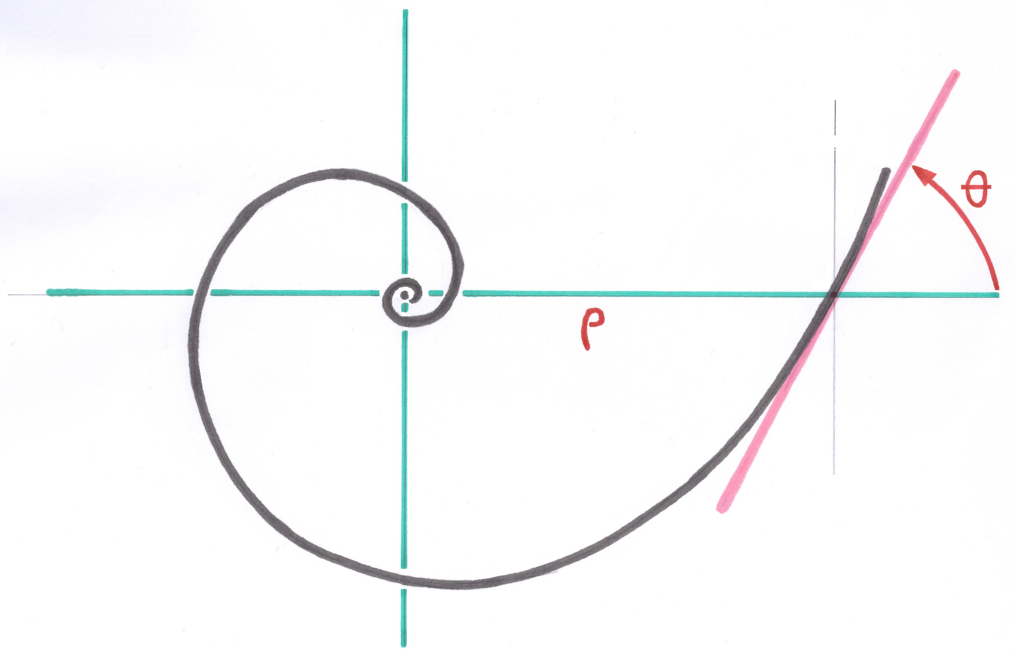
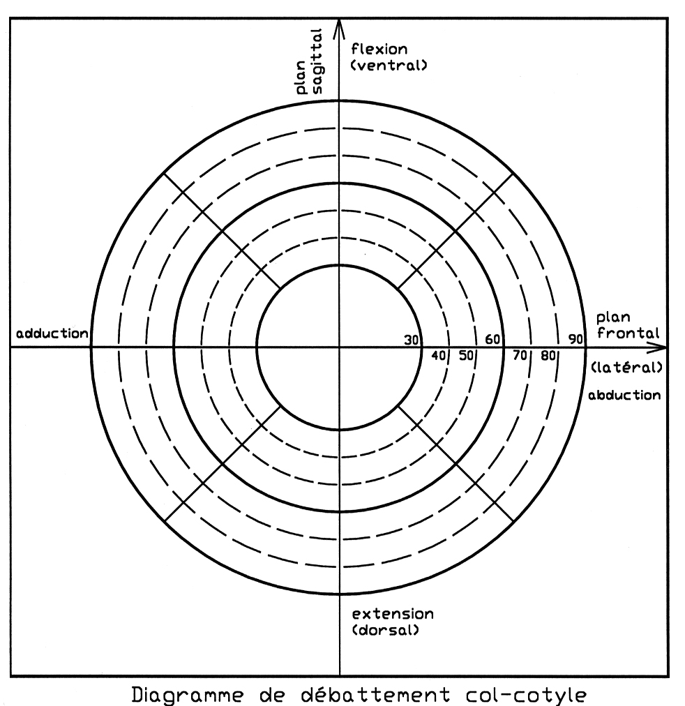
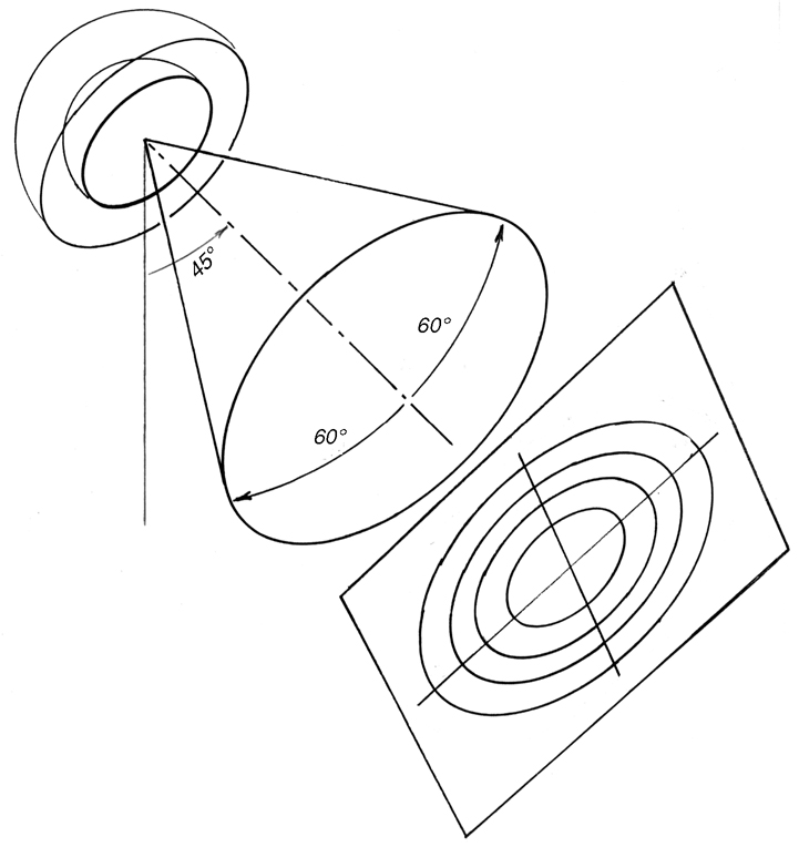
Subsequently, in 1998, I added to the proposal for Standards on conical junctions of heads, a proposal for a standardized process to designate geometrically in 3D, the map of the amplitudes of movements in all directions for a given combination between acetabulum, neck and head and which takes these factors into account inseparably with a fairly readable graphic representation. This process derived from my experience with visual field measurement used in ophthalmology. The details and examples can be consulted in article 6.7.2.3., pages 20-22, §3.3.3.-3.3.6, in particular Figures 3.3.L and 3.3.M.
5.3.3.6. Graphical Visualization of Neck-Insert Deflection
Subsequently, in 1998, I added to my proposed Standard on Conical Head Junctions a chapter defining the diagram representing the deflection amplitudes around the acetabulum axis in all directions for a given combination of acetabulum, neck, and head. All these factors are taken into account in a fairly readable graphical representation. This process was derived from my experience measuring visual fields used in ophthalmology.
5.3.3.7. Comparison with "hooded" inserts
Inserts with an additional raised portion of their periphery, called the "visor" or "hood," are primarily intended to retain a head that is in the process of dislocating. Assuming this works, there is nothing on the half diametrically opposite this "hood" to prevent the onset of dislocation.
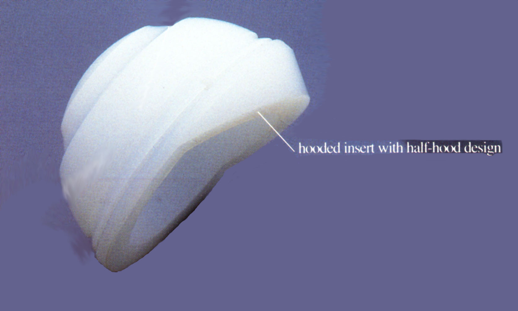
Most of the time, the "hood" (visor) is not a continuation of the sliding hemisphere but only a cylindrical area of the same diameter as the hemisphere and parallel to the main axis of the insert. This allows at least the head that is beginning to dislocate to return to its place. According to the graphic representation of the proposed Standard 9.7.2., page 21, § 3.3.5, "hooded" inserts have a lower total travel than flat inserts of the same size. page 22, fig.
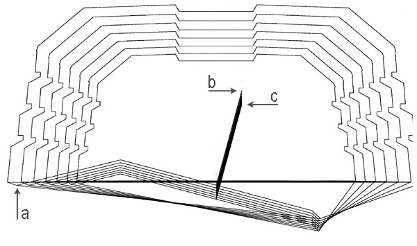
5.3.3.8. Design of the Inlet Cone
I call the surface immediately surrounding the hemispherical sliding zone the inlet cone. This conical surface is an excerpt from a cone of revolution whose axis is the axis of inclination of the sliding hemisphere relative to the main axis of the shell. This inclination is 15° for the polyethylene insert and 12° for the metal-on-metal insert.
I found no reason to introduce a discontinuity based on a diameter, i.e., one half completely flat and the other half inclined, as in so-called "hooded" cups.
This refers to the boundary surface that the upper end of the neck, near the cone junction receiving the head, could encounter in the event of extreme deflection. In this case, the conflict of extreme deflection would occur between a fairly large area of polyethylene and the region of the neck that has not been ground or roughened.
In my design, I avoided having the polyethylene surface encountered by the neck in the event of extreme travel, having a shape that would cause point contact, to limit the early production of wear debris. It is better if the contact occurs on a segment. To complete this precaution, I planned to leave the neck of the stem polished near the cone.
5.3.3.9. Slight axial lift in small sizes
In all my inserts, whether flat or Antilux, I maintained a protrusion of about a millimeter between the insert plane and the shell entry plane. The goal was to ensure that under no circumstances would a metal part of the stem come into contact with the titanium edge of the shell, again to avoid the risk of wear debris.
If I had strictly preserved, as in the flat inserts, the geometric center of the head in the shell entry plane, which defines the level of the origin of the coordinates on the shell axis, which is also the Center of Growth, I would not have been able to achieve an inclination of the head entry plane of 15° or even 12° for all sizes, without the neck risking coming into contact with the edge of the shell for small sizes.
For small insert sizes that had a restricted polyethylene width between the shell and the sliding hemisphere, the inclined inlet cone met the edge of the Titanium shell.
I therefore had to trigonometrically establish a slight axial exit from the center of the head, taking into account, for each size, the residual thickness of polyethylene so that the inclined inlet cone could not encounter the titanium edge of the shell, but also to maintain an additional thickness of polyethylene protruding from the shell. The consequence of this exit from the center of the head for small sizes is visible radiologically. This is in no way a lateralization decision.
5.3.3.10. Eliminating the Loss of Range of Motion
Without exception, no insert on the market designed to reduce dislocations actually delays the lever action of the neck on the curb. Some, such as the Zweymüller AlloPro angled inserts, cause dislocation even earlier than flat inserts and result in a loss of travel.
The design I introduced for the Bicon system's Antilux insert, with the fundamental recessed entry cone and full tilt of the sliding hemisphere, allows the neck's range of travel to be maintained within the insert. The result is a change of direction of approximately fifteen degrees. The travel, which was approximately 128° for the standard flat insert, thanks to the slightly tapered neck under the head's connecting cone, is fully preserved with the anti-dislocation insert.
5.3.3.11. Observations on Instrumental Placement
Implementing the Antilux insert into the shell using the long-handled inclined insert holder appears to be a source of poor positioning. Manually positioning the insert in the direction previously defined by the trial insert is more reliable.
The operator has a better tactile feel for the placement of the "multi-cone" junction in the shell by performing a few small rotational movements around the chosen orientation, and can feel when the junction is established. Only then does a rimless spherical impactor complete the fixation. I do not recommend using a long-handled cup holder, which eliminates any tactile sensation.
5.3.3.12. Precautionary rule: Limiting the maximum inclination of the neck
By sinking the crater formed by the insert's entrance cone on the side opposite the cover elevation, it is generally possible to achieve surprising inclinations of around 75 degrees.
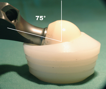
I imposed the following rule as a limitation to this maximum travel: the direction of the force exerted along the axis of the neck must never pass outside the metal shell receiving the insert. This rule prevents the development of forces that could cause the insert to tilt out of the shell.
An insert secured by a conical junction must always operate under axial compression, even if only slightly. Since 1991, when I the Multicone Junction created, I have observed the reliability of these inserts' fixation, which far exceeds my most optimistic expectations.
Moreover, the Multicone Junction has since proven sufficiently resistant to traction, and retentive inserts have been produced.
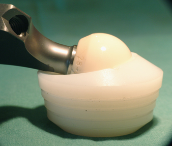
5.3.3.13. Protection of the edges of the sliding seats
The sliding seats included in the polyethylene, in the "sandwich" technology of the Metal-Metal inserts, or the Ceramic-Ceramic technology of the Antilux inserts, must not be able to contact the neck of the prosthesis. I designed the polyethylene parts intended to receive the metal or ceramic sliding seat with an additional edge near the periphery of the sliding seat. This additional edge prevents direct contact between the metal neck of the stem and the edge of the sliding seat, a contact that would be a source of metal wear debris.
----
Next implant: