5.5.1. Spiral Reamer for Modular stems
5.5.1.1. Thinking that led to the creation of the Spiral Reamer
The principle of this reamer appeared only after the complete design of the stem of reoperation of third intention Modular Plus.
After having studied all the characteristics which were to compose the future stem Modular Plus and dictated line by line the schedule of conditions of the future Modular system, at the time of a voyage only intended for that, I did not have an precise idea yet to compose the instrumentation which would be used for this prosthesis.
The Spiral Reamer is a creation that still surprises me to this day. The totality of the intellectual process of creation proceeded of head, without any paper medium or computer software. I was not at all persuaded to be able to join together and make cohabit all the ideas on a single object, nor that this object would be technically realizable.
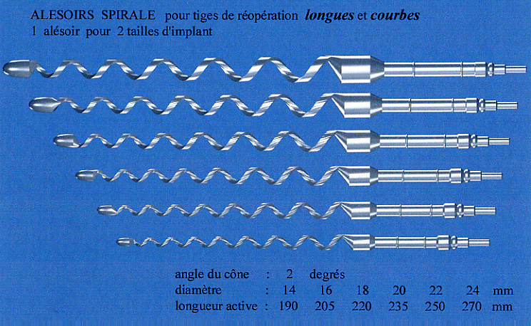
Requirements for the preparation of the femur to implant the anchor rod of Modular Plus were unique. It is an extra long shank section which widens regularly from the tip to the proximal portion. The idea was to get a cementless fixation satisfying all my Principles of the Geometric Anchoring.
5.5.1.2. The traditional rasps are not appropriate
I had noted at the time Protek-Sulzer used a toothed rasp of the same type as the stems of Zweymüller requiring to rasp with a coaxial hammer, for an extra long prosthesis of reoperation intended to cover the same field as the Modular Plus prosthesis. It appeared to me that the preparation would be very incomplete with this rasp being given its big length and the multiplicity of the teeth,
and thus that it was not possible because of many simultaneous contacts to work the interior cortical surface without applying extremely violent shocks who could have serious consequences, such as for example cracks. A rasp of the same type with few teeth would not have presented these problems but would have produced a preparation in stair steps which would have had like consequence a resorption of the bone at the contact points and a descent of the stem was foreseeable. My wish was to obtain a much more regular preparation than that which one could obtain with toothed rasps.
5.5.1.3. Problems to be solved
The first selected option was to seek a turning instrument which allows a much less shocking preparation that the use of the toothed rasps. The Modular stem required to prepare the bone with a conical form to obtain a junction as close as possible to the traditional conical junction on a very big length, i.e. about thirty centimetres.
Over this length, the femur always presents an important anterior curvature which would thus require for a too large instrument to preserve a very clear flexibility to be able to follow the curvature of the femur, the flexibility being necessary so that the instrument becomes deformed during rotation.
In an imaginary way, it was possible to also extend this conical form with this line rolled up around the cone to a curved conical form curved itself on an axis in logarithmic spiral curve. If this form were realizable, we could obtain the ideal instrument.
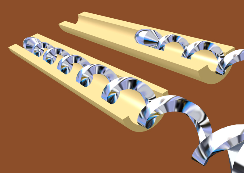
In an abstracted way, without being able to make drawings or calculations, it appeared useful to lay out the sharp blade of the instrument along the logarithmic spiral curve laid out at the surface of the cone presenting a constant angle in 3 dimensions with the frame of reference, which would make it possible to remove chips inside the cavity simultaneously when the instrument turns around its axis and that the Operator presses in the direction of the axis on the instrument and that it exerts an axial pressure. It was necessary moreover to evaluate, in an abstracted way, with which approximate slope one would obtain a reasonable distribution between the force obtained by rotation and the force obtained by the axial pressure so that the blade detaches a relatively regular chip in the bone.
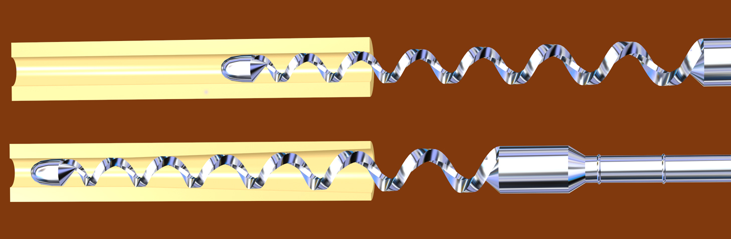
An extremely important consequence of this arrangement is that the spiral must be in the opposite direction of all existing screws, with share the screws turning left, so that rotation being carried out in the traditional direction, that the instrument does not seek to progress forwards and to be blocked, but to move back and to some extent “to unscrew themselves”. By reversing the direction of the spiral compared to the normal direction of rotation, if the axial pressure applied is zero or low, the instrument tends to remain on the spot or to move back with the least friction resistance on the surface of the bone.
It was necessary to define the inclination of the cutting line relative to the rotation by seeking a compromise between a too stretched spiral in a direction parallel to the axis of the insrument, that would simultaneously exhibited a too strong resistance against the rotation as in the preparation being effective, the entire line is spiral in the working position against the bone, and all points of the spiral working simultaneously.
In addition, if the spiral has a too small step, the effect of cut is lower and the effect of retreat takes the top, with the result that one does not obtain an attack of the bone. Moreover, if rolling up is too tight, there is a too big linear length of sharp edge vis-a-vis the bone what decreases the effect of the pressure to obtain an attack by the sharp blade.
It was not possible to establish, negotiate and find a compromise for an experimental method as a preliminary since it was necessary to produce the instrument initially what was an immense difficulty, and to produce several instruments with several angles would have been prohibitory in expenditure and work of Laboratory. Therefore, I chose to solve this problem only by the reflection.
Another property of the sharp part of the blade is on the other hand well-known from specialists in milling. This is the angle of attack of two surfaces on both sides of the sharp line of the instrument so that the instrument penetrates in the bone and removes a chip without however go deeply in the bone. These two angles are known for various metals which undergo numerical millings in particular. For the bone, which does not behave like metals and whose chips are particular because of composite nature (inclusion of a crystalline zone in the osseous cell), it is the observation of the chips which enabled me to choose these angles.
We must also take into account the speed of rotation of the instrument during the work in the bone.
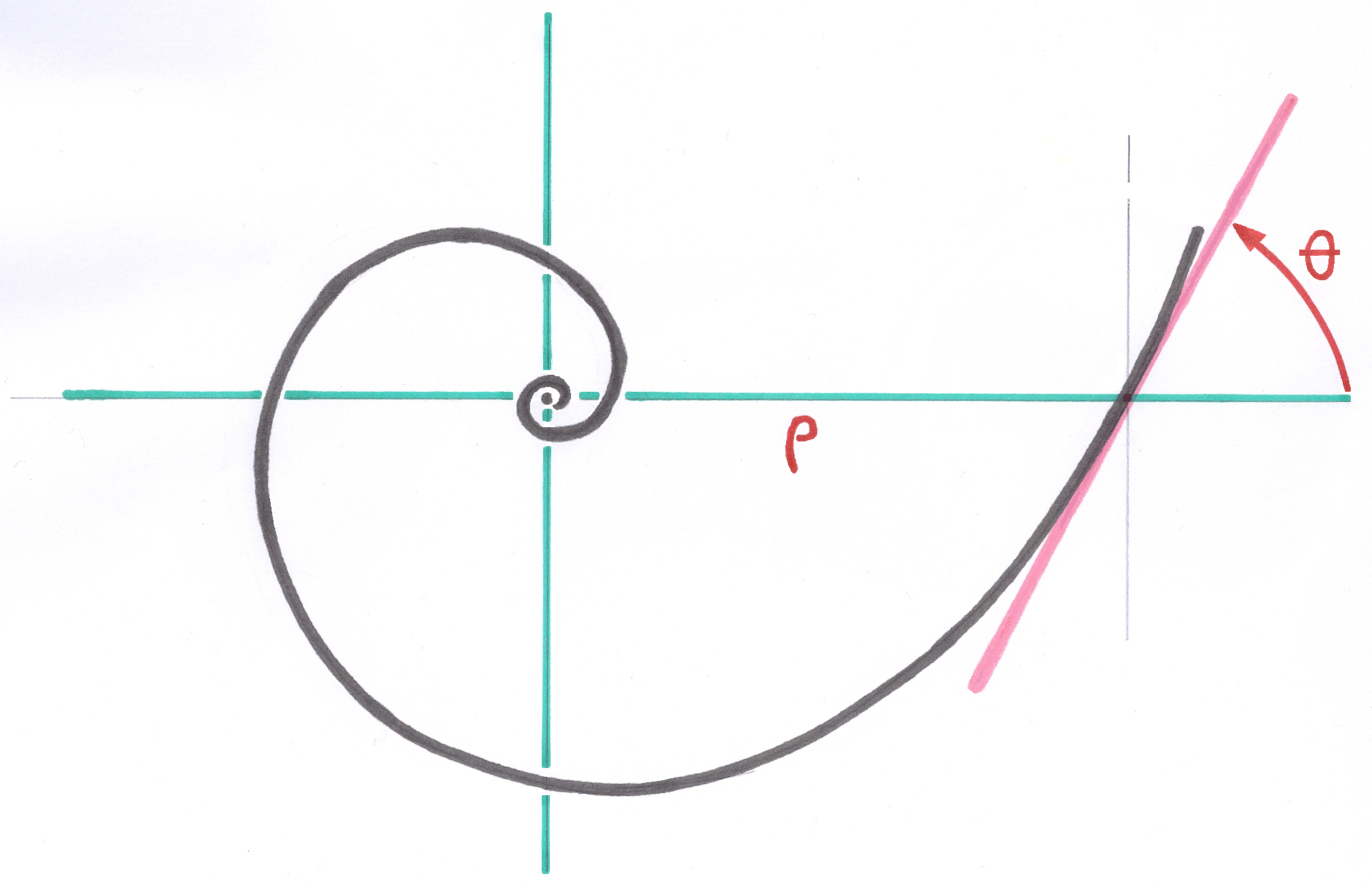
I would like to pay homage to my Mathematics professor Mr Dupin, who came from the Ecole Normale Supérieure and who, for the last year in Special Mathematics, taught, 50 years ago, the space geometry and the descriptive geometry. His course on the logarithmic spiral curve had marked me and the essential properties of this spiral had clearly remained to me in memory, in particular the conservation of the angles. This is the angle of the tangent in a point with the radius-vector (radius-vector which will be defined later).
I had the chance to think to generalize to 3 dimensions the logarithmic spiral curve, generalization which was taught at all neither on this level, nor in Faculty of Science thereafter, the spiral logarithmic curve being intended only for exercises intended to make difficult the work of the pupils, and whom only one application is known for me. (Linear Condensers)
The generalization of the logarithmic spiral curve to the third dimension i.e. that the coordinate in Z also varies with an exponential function could appear a very interesting property but which appeared only in a strictly imaginary way and I put forth the assumption of the possibility of a spiral 3D with permanent conservation of the angle of the tangent also in Z compared to plan X Y.
Another property which appeared but, at this time, without still being proven mathematically was that this logarithmic spiral curve in 3D was registered on a circular cone whose origin was the origin of the coordinates. The asymptotic pole of this spiral 3D is confused with the origin of the coordinates.
These interesting properties at this time still purely imaginary enabled me to establish the link with an instrument which would exploit these properties.
5.5.1.4. Bending in rotation
The thickness of the active part of the reamer is also increasing logarithmically so that the general elastic curvature is in the form of a logarithmic spiral when the distal olive meets the obstacle constituted by the curved wall of the femur.
The flexible version becomes essential as soon as one wants to prepare the medullary canal beyond the medium of the total femur. With the Spiral Reamer, the trajectory of the point is not completely any more independent of the direction of the handle or the engine, as it is the case of the instruments assembled on very flexible springs. So one should not let the instrument direct itself its handle. The handle plays a more precise part here than the only transmission of axial rotation.
5.5.1.5. Use of the flexible “Spiral Reamer”
The flexible Spiral Reamer is the only instrument allowing a controlled preparation of the medullary cavity, to obtain a form associating perfectly definite conicity and regular anatomical curve.
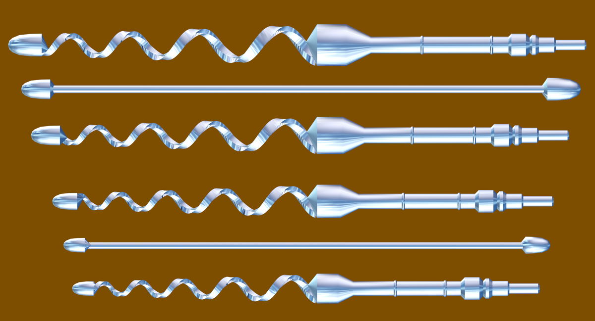
The reamer is always provided accompanied by a gauge comprising an end in the olive shape whose diameter corresponds to polished olive being with the point of the reamer itself. It is used to test the unrestricted passage of the olive of the instrument.
A very visible arrow engraved on the cylindrical proximal section indicates the normal and obligatory direction of rotation.
In certain cases, to see below, a passage for the olive must be obtained preliminary by any manual or motorized instrument, and the other intramedullary osseous obstacles must be removed.
The instrument must turn slowly: its principal use is manual, with a handle, but connection with a surgical motor equipped with a speed-reduction gear is possible. The experiment showed that a fast rotation gets a lower or bad result.
It is clear that the instrument does not prevent the operator from continuing with excess the preparation (as it is the case of any sharp instrument) and than only the operator is judge of the sufficiency of the remaining osseous capital, on the basis of preoperative planning and attentive observation of theX-rays.
The instrument cuts only if the operator applies an axial force during rotation. When the axial force ceases, the instrument ceases to cut. The instrument can not exceed the defined depth and does not continue to cut during the few moments that requires stopping the engine, unlike all the existing tools of drilling and milling.
A rotation of the instrument, always in the one way on the right, but without exerting axial pressure, causes its exit while moving back. In the same way, a hard obstacle met causes also its retreat.
If the unrestricted passage of the safety olive, the instrument by his conicity and the winding direction of his spiral, cannot block itself, since for a conical form, any retreat corresponds to a reduction in local section. An arrow engraved on the cylindrical proximal part proximale indicates the normal direction of rotation. Opposite rotation is strictly prohibited because it is only in this case that the instrument can be blocked. A right rotation makes it possible to free and remove the instrument.
5.5.2. Complements of operative technique
5.5.2.1. Determination of the quantity to ream in-depth
As 1cm of axial progression corresponds to 0.35mm in increase in diameter, it is necessary to take care to preserve more than 2.5 mm of intact cortical on all the periphery of the femur after preparation. It is necessary to carry out approximately 8cm correctly reamed area in a conical way for a good primary stability of the implant in the femur. For that, starting from the first blocking of the reamer, make slowly turn the reamer to progress of at least in-depth 8cm to obtain a sufficient boring.
In the cases of reoperation where the distal fixing of the stem needs really the third distal quarter of the femur, a stem of a rather large size can be necessary. In this case, the proximal part proximale of the corresponding family of stems may be a little bulky to be contained in the proximal part of the femur. It may be necessary, carefully and gradually to widen the proximale part or to open a sufficient front flap, consolidated by a titanium strapping.
5.5.2.2. Respect of the anterior curvature of the femur
Application of a flection on the reamer during reaming
The reamer must be maintained by bending the handle into dorsal (of femur) and the distal olive pressing the anterior cortex. That practically corresponds to the catch in hand of the instrument and its engine to the manner of a fishing cane. One thus corrects the natural tendency of the instrument to recover in straight line, and one saves cortical former the proximal former cortical, often rather fine to the base of the neck of the femur. At the same time, the dorsal part of the metaphysis is correctly prepared, in curvilinear alignment with the femoral diaphysis.
5.5.2.3. Précautions of use
If you checked the unrestricted passage of the safety olive, the instrument can practically never be blocked in the femur. By its shape in inverse spiral, the reamer can never be blocked during rotation. By its perfectly conical surface-envelope, it cannot block in the also conical cavity being prepared, because when two conical surfaces, of the same angle, differ very little along the axis, no close contact occurs.
In certain cases of reoperation, abrasive cement remainders can damage the edge of the instrument. All cements comprise a powder opaque to x-rays of a very great hardness. Take care to extract the totality of the cement.
It is the same of the remainders of implants, screws, pins. Take care to extract the totality of the remainders of the old prosthesis.
5.5.2.4. Removal of the chips
The Spiral Reamer, during the operation, product small chips of bone. Because of the inverse winding of the spiral, these chips are naturally pushed back towards the point of the instrument and the bottom of the bone cavity. I recommend removing the instrument after each centimetre of in-depth progression and to remove it from the chips with a wet compress.
5.5.2.5. Cleaning of the Spiral Reamer
The Spiral Reamer must be cleaned separate and not collides with other instruments. For the Spiral Borer, all the length of the edge being active simultaneously, no zone must be damaged. Do not use abrasive pads because the cutting edge would be blunted.
5.5.2.6. Sterilization of the Spiral Reamer
The instrument owes, before each use, being sterilized exclusively in autoclave with 137°C or 2 atmospheres. Sterilization in dry heat is excluded because it is likely to damage the cutting edge and the quality of hardening of steel.
5.5.2.7. Handling of the Spiral Reamer
After washing, the Spiral Reamers must be immediately replaced in the sterilization plates and transported in the cells which are intended to them.
5.5.2.8. Orthopedic Gloves
As with any cutting surgical instrument, the thin rubber gloves can be damaged. To use the Spiral Reamer, it is advisable to insert between the gloves an orthopaedic glove in jersey which resists to the sharp instruments.
5.5.3. Special orthopedic situations
5.5.3.1. Damaged and fragile diaphyses
In these cases of deep reoperations, the loss of proximal osseous capital is the primary reason of the use of deep implants requiring a distal fixing, therefore the use of the Spiral Reamer.
Cortical zones are thinned, perforated, fissured or even missing and the preparation for a new implantation takes place in fragile zones. It is normal to set up, preventive and before beginning to ream, 1,2 or 3 strappings in Titanium ribbon, so that the internal pressure during reaming does not cause a crack.
Steel or metal other than titanium straps or wires should not be used, as electrolysis phenomena occur between two metals separated by a conductive medium.
In certain cases, it can be interesting to recover and filter the osseous chips to use them like filling paste.
5.5.3.2. Atypical Diaphyses or narrowed medullary canal
Frequently encountered cases of reoperation where the medullary canal is significantly narrowed in the region where the tip of the preceding prosthesis was. In certain cases, the medullary canal is completely closed by newly formed bone, often named a “pedestal”. These two cases require a particular attitude before the use of the spiral reamer.
5.5.3.3. Where the diaphysis is only narrowed
This case is identifiable on preoperative radiographs, and must be planned.
In Planning
It is necessary initially, with the olive gauges , to define the size of olive corresponding to the part of the intact diaphysis located distal of the narrowing. That is to say for example the olive B chosen thanks to the olive gauge applied to the radiography. On the other hand, only the A olive gauge can cross the narrowing observed on radiography.
In operation
After complete extraction of the cement with any available instrument, except the spiral reamer, test the channel with the olives A then B.
If, as expected, the olive A passes through the contracting, use the reamer A to begin the preparation, and continue the taper reaming until the progression of the reamer to the mark A4, by cleaning several times the chips. Thus, the contracting is widened by the reamer having created a conical interior surface in the diaphysis instead of an unspecified zone non compatible with the anchoring of a conical stem. Then only use the reamers B or more to obtain the conical preparation until the planned size and over the planned length.
5.5.3.4. Case where the diaphysis is closed
In Planning
The pedestal of newly formed bone under the distal point of a former prosthesis occurs at six to ten years, for cemented or cementless stems. It belongs to the osseous reorganizations caused by the prosthesis. As of planning, it is clear that the reamer, of the final or lower size, will not be able to cross a pedestal because it is not intended for drilling.
In operation
Use a drill of 10mm, for a rather rectilinear channel, or a drill of 10mm on flexible axis for a curved channel, to cross the pedestal. That gives the passage for the olive A, and it is with the spiral reamer borer that the contracting of the channel will be gradually widened.
If for example the size of planned distal stem is planned C9 or even C11, it is necessary to ream gradually with the reamers A, then B then C. I point out that for the not narrowed channels, the final reamer must be used from the start.
5.5.3.5. Case where the diaphysis is in “bayonet”
I evoke here the cases after osteotomy or not aligned consolidation of an old fracture. A control with the brightness amplifier is careful to check the passage of olive A initially and then of the A reamer. During the continuation of reaming, the channel gradually tends to regain a continuity of curvature.
5.5.4. Properties of the Spiral Reamer
5.5.4.1. Choice of the metal alloy
The selected alloy is especially adapted to the realization of the Spiral Reamer thanks to its simultaneous properties of hardness, aptitude for the sharp instruments and having a good elasticity, while allowing the deformation before the rupture and finally its good corrosion resistance.
5.5.4.2. Heat treatment
The heat treatment is practiced on the already turned outlines, but before the realization by grinding of the precise geometry in spiral. It thus ensures the totality of the metal part a homogeneity of mechanical properties much larger than a tempered finished instrument of great variations in the local thickness of matter, as it is still the case for many instruments.
5.5.4.3. Production of the Spiral Reamer
The total numerical grinding in the mass of the instrument with a precision of a few microns guarantees the best correspondence currently accessible between the coordinates calculated as a preliminary by computer and dimensions from the finished instrument. I did calculate and send micron precise coordinates to the producer. Each instrument requires approximately four hours of numerical machining on an enormous exceptional and single machine. A heat treatment, after grinding, would have caused unacceptable deformations for the function and the safety.
5.5.4.4. Fastening coupling
The instrument is planned for a use on an orthopedic engine having a hexagonal connection of 12mm, but also possibly with a handle with a snap-on hand grip.
The engine must be equipped with a speed-reduction gear as it is the use for the spherical reamers for cups, at the speed from 1 to 5 turns a second, but not more.
My experiment showed that the snap-on quick couplings present some failures: loss of screw, springs, balls.
To be able to finish the preparation of the bone in the event of use of an engine and breakdown of connection, at the end of the axis, is envisaged a safety fixing consisted in a cylinder of 6mm diameter and 15mm length, comprising 3 small flat parts to prevent slipping during rotation, which can be tighten in a traditional chuck with 3 nozzles.
5.5.4.5. The risk of blocking is almost zero
If the medullary canal has a narrowing of the free passage diameter, the olive could be subject to mechanical blockage due to high friction. In this case only, the thinnest part, towards the tip of the instrument, would be subject to torsion with a risk of breakage at the base of the olive. Measure taken against this risk: Each instrument is supplied with an intramedullary feeler in the shape of an olive attached to the end of a relatively flexible metal rod, the use of which is mandatory before introducing a new size of reamer to ensure that the olive of the instrument is absolutely not at risk of becoming blocked, and this throughout the medullary canal.
In the unlikely event of blockage during normal use, with normal speed and direction of rotation, release is achieved by rotating, always in the normal direction of rotation, with a 12mm Allen wrench or a multi-grip wrench. In this situation, the coils tighten by a fraction of a millimeter and contract in place, causing the instrument to release and recoil.
The "reverse gear" available on some surgical power tools on the market should never be used with this instrument.
----
Next instrument: