5.2.3. Stems Holz-Zacher-Deckner
5.2.3.1. The Cemented Straight Stem with the Most Innovations
During reoperations, I had observed a number of imperfections in the straight stem Müller that I wanted to correct with the cemented Holz-Zacher stem. By applying as many of the methods I had developed for cementless stems as possible, I was able to achieve my goal.
5.2.3.2. Anteroposterior Thickness Variation and Comparison with the Müller Stem
All sizes in the Müller stem series had a single proximal thickness. Toward the tip, this thickness decreased slightly distally, without a specific angle.
The anterior and posterior surfaces performed no intended function in compressing the cement toward the anterior and posterior bone walls during implantation.
The medial and lateral contours of the anchoring zone were designed to meet the bone wall at 3 or 4 contact points. It is because of this bone wedging at a few points that this stem was commonly referred to in France as the "Müller self-locking" stem. At these points, the cement mantle was nonexistent.
5.2.3.3. The importance of cementing grooves
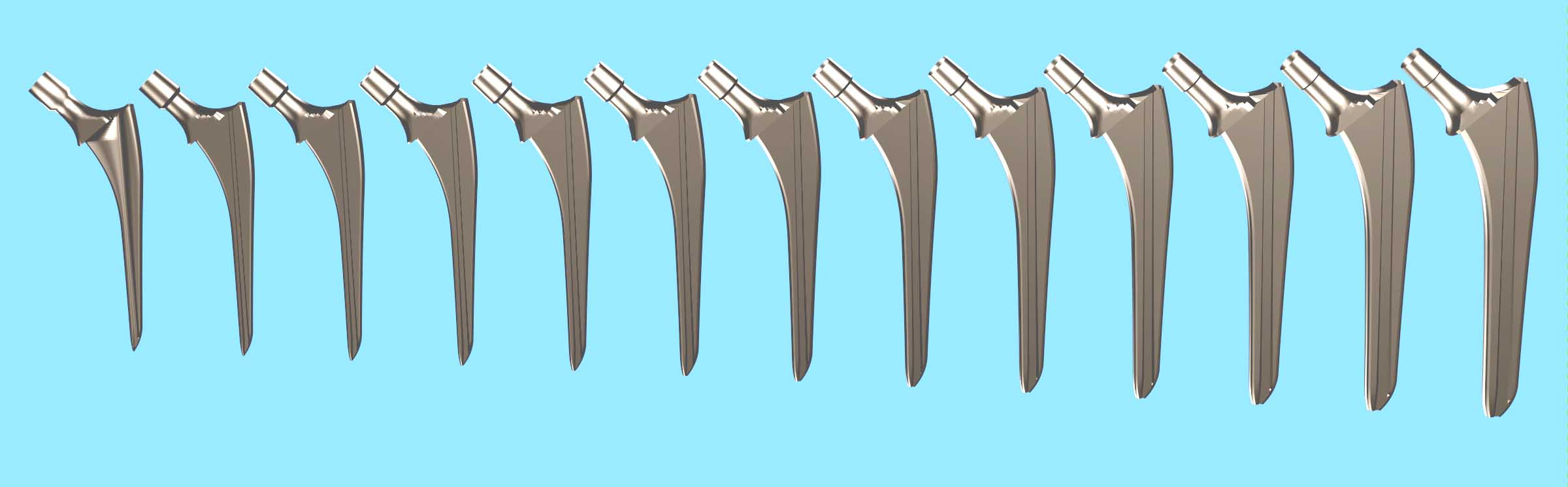
As in cemented Müller stems, the longitudinal grooves in cemented Holz-Zacher prostheses serve a stabilizing role within the cement sleeve. However, in Holz-Zacher prostheses, the grooves play a much more advanced role, allowing for a gradual increase in cross-sectional area. The grooves are deeper distally and their depth decreases steadily toward the proximal end.
Thus, the grooves compensate for the increased lateral cross-section brought about by the Fixation Function, which has a greater amplitude than cementless stems. Thanks to the grooves, the cross-section varies more to achieve peripheral compression of the cement.
These grooves of variable depth make it possible to separate, on the one hand, the adaptation of the cemented stem to the general shape of the medullary canal, and on the other hand the ability of the stem to distribute the cement harmoniously, in particular to avoid the break in continuity of the cement sheath by piston effect.
5.2.3.4. Groove Inclination for Extractability
To further satisfy the Principle of Extractability, the groove is inclined relative to the construction axis of the anchoring zone and made parallel by calculation to the medial contour of the anchoring zone.
The grooves widen steadily toward the tip of the stem. The flat surfaces of the groove bottoms also become closer together distally. In hardened cement, the groove surfaces behave like a tapered joint.
As with any conical junction, any start of extraction over a few millimeters causes the simultaneous separation of the prosthesis and the cement on all surfaces of the grooves.
At the start of extraction, the stem is guided as if by rails and forced to translate in the medial direction shared by the medial contour and the groove. As a result, the entire lateral contour moves away from the cement sheath. This distance protects the greater trochanter from the risk of cracking, compared to a vertical extraction. The inclination of the extraction thread contributes to this medial extraction.
5.2.3.5. Trochanteric Curvature
The trochanteric region of this stem was calculated with a moderately large curvature and not along a broken line.
I had observed on several occasions that the trochanteric region of the straight Müller stem did not meet my Extractability Principle. The broken-line lateral contour was unacceptable to me. This oblique segment was unfavorable for regular cementing during implantation and unfavorable for stem extraction in the event of reoperation.
I am pleased to note that the trochanteric aileron has recently been removed on the minimally invasive Zweymüller stems, for the same reasons, removal of the conflict with the greater trochanter.
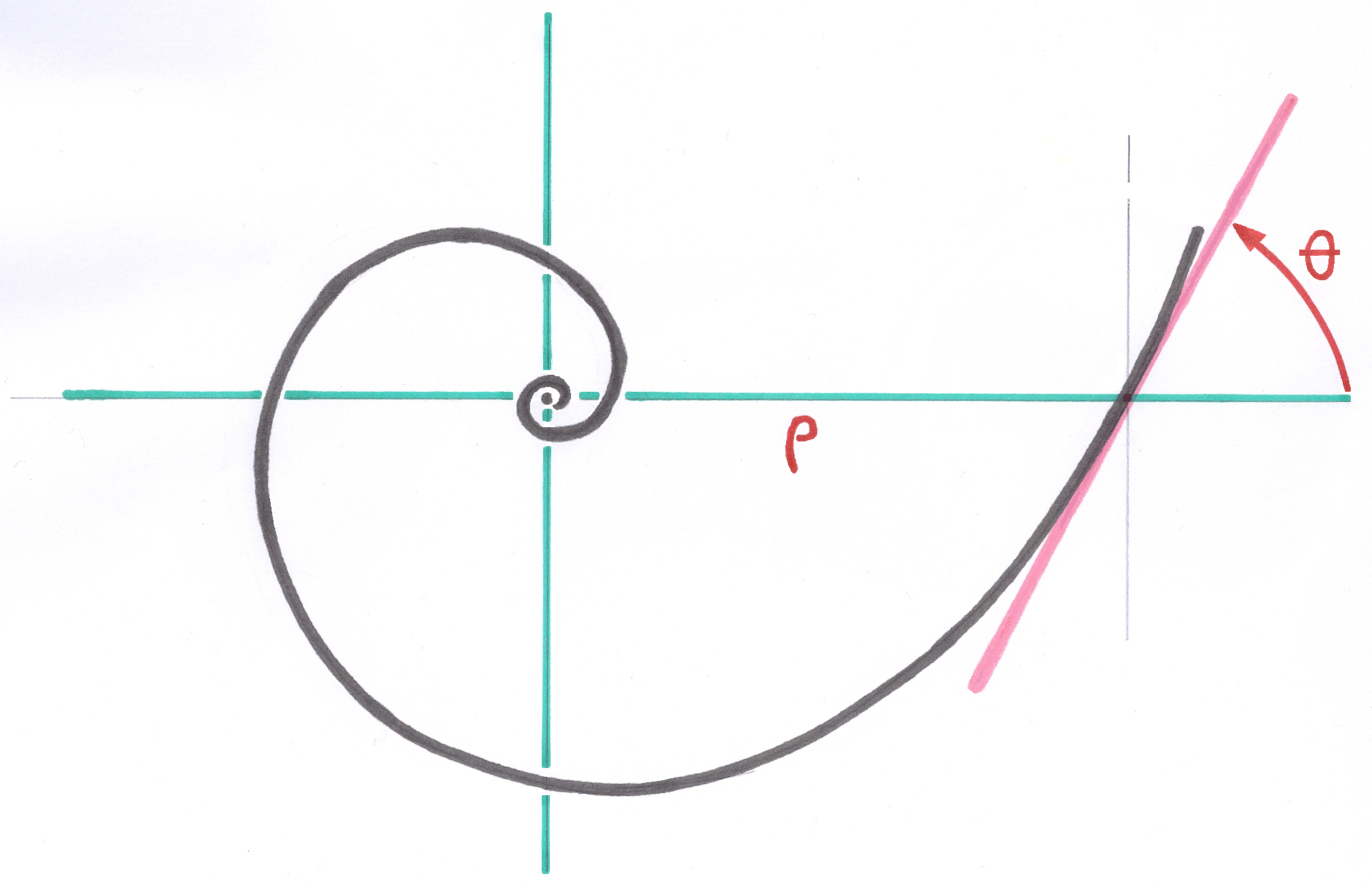
5.2.3.6. The Calcar Curve
The Calcar curve was calculated using an automatic parameter definition process for the exponential function that defines all its points.
5.2.3.7. The collar and its inclination
Professor Holz recommended that the neck section of this cemented stem be cut at a moderate angle. The collar of this stem was therefore calculated with an inclination of 40° from the horizontal.
The narrow collar, while contributing slightly to the compression of the cement at the end of implantation, provides a positioning reference for the operator.
5.2.3.8. The Lateral Contour of the Stem
The entire lateral contour is composed of a series of functions, described below, in the same way as the entire Calcar Polynomial for the medial contour.
This lateral contour is formed as a polynomial whose first term is the Pyramidal Base Shape. These are successively added: the trochanteric spine curvature function, a fixation function similar to that of the medial contour but with a more pronounced amplitude parameter, and finally the Distal Ski function, specific to cemented stems.
I have not given this set of functions a specific designation.
5.2.3.9. The inclined extraction thread and extractability
The extraction thread is geometrically identical to the thread I applied to all the rods in my design. I would have liked it to be the subject of an International Standard.
The extraction thread was inclined approximately ten degrees toward the neck. This direction is similar to the slope at the top of the trochanteric spine curve. If the prosthesis needs to be extracted, during the first few millimeters, the direction of the traction shocks applied to the extraction screw is unlikely to cause cracks in the greater trochanter.
Had the extraction thread been vertical, in the direction of the longitudinal axis used to calculate the stem, the immediate effect would have been a risk of cracking. The millimeter elasticity of the greater trochanter and the cement surrounding the stem in this area will be minimally stressed, yet without breaking them. Only the first centimeter of trochanteric cement will need to be extracted beforehand, unlike the cement of straight Müller stems, which must be removed up to the bend of the lateral contour.
5.2.3.10. Cement Progression Dynamics
As one might expect, I did not have the laboratory resources, supplemented by hydrodynamic methods, which are beyond my expertise, to be able to define or perform simulations on the phenomenon of viscous cement behavior during rod progression.
In return, my hundreds of observations during hip and knee stem implantations have given me a good understanding of the dynamic behavior of cement.
I had to think a lot and imagine the phenomenon to finally find the optimal stem shapes and then formulate and program the corresponding model.
The shape of the prosthesis had to ensure that the cement, during the insertion trajectory, would not undergo any longitudinal centimeter displacement, either during insertion or during ascent.
Ideally, a drop of cement, if it could be locally identified and tracked, would only move in a plane perpendicular to the implantation direction.
This displacement includes the insertion into the crevices of the medullary canal and into the spongy residue of the proximal zone. Also, a balancing of the distribution around the stem.
The acceleration of the increase in the stem's proximal cross-section was intended to prevent cement reflux and provide cement compression at the end of implantation.
This consideration includes the presence of a diaphyseal obturator equipped with a drain connected to the suction system.
5.2.3.11. Cement Sleeve Continuity
Many cemented stems have a massive cross-section at their distal tip, which creates a piston effect on the cement. When the distal tip reaches the area where the medullary canal is no longer significantly wider than the tip of the stem, the cement beneath this tip is pushed distally and ceases to distribute around the tip. There is a break in continuity precisely in the area where it is essential.
A diaphyseal obturator normally solves this problem with most stems. For the Holz-Zacher stem, the distal tip section has been significantly reduced thanks to the recess provided by the cementing grooves. The I-shaped distal tip section allows the cement to distribute itself around the stem tip. The piston effect does not occur.
A centering accessory attached to the tip of the rod and featuring fins is not required. This accessory, while keeping the tip radiologically centered in the medullary canal, causes a longitudinal cut of the cement sleeve into four or six strands, which eliminates the mechanical continuity of the cement sleeve.
There is also no cut into six sectors by the fins of a centering accessory.
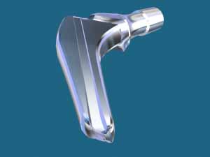
5.2.3.11. The Neck
The neck, comprising the cone connecting the spherical head, was designed incorporating all of my principles. The intertrochanteric turning area has a catenary-shaped profile (hyperbolic cosine), as Gaudi used it in his architecture.
This shape ensures the best possible fracture resistance of this area for each size.
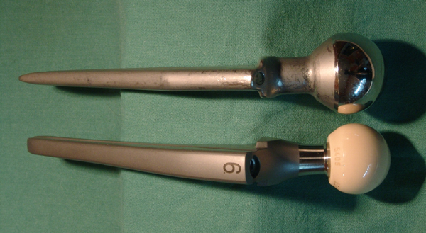
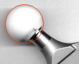
5.2.3.12. The head's connecting cone
The standard 14 connecting cone with the ceramic head complies with the Sulzer patent for the structured cone, whose slightly deformable surface is designed to grip the inside of the ceramic head's connecting cone and, above all, compensates for very small manufacturing differences in the geometries of the metal cone and the ceramic cone.
I am a fervent advocate of this technology, which I called "microstriations" as early as 1978. I persistently defended this technology in the meetings of the Standardization Commissions, and after this patent entered the public domain, I insisted on including it prominently in my proposal for a European standard encompassing all the issues that arise regarding conical junctions in orthopedic implants.
5.2.3.13. Pivoting Range
The Holz-Zacher stem neck was designed to provide the greatest possible range of movement relative to the acetabulum. The concept and graphical representation of movement are provided in chapters 3.3.3. to 3.3.6. of my draft Standard (6.7.2.3.).
The neck immediately below the base of the junction cone has a smaller diameter than the cone to increase clearance and provide leverage as late as possible with the entry of the spherical area of the acetabulum. The neck diameter of each size varies slightly thanks to a specific Growth Factor to statistically account for the resistance required by patients of very different sizes. The influence of this variation is only about one degree on the range of clearance. I did not find it reasonable to use even thinner necks to increase clearance because other conflicts, such as contact of the stem with the edge of the shell, could become possible.
The axial length of the active zone of the cone joining the head has been reduced so that the base of this cone can never come into contact with the edge of the spherical zone of the acetabulum. To this end, the lowest point of the cone joining must never be outside the sphere-shell of the spherical head for any neck length in the spherical head family. Obviously, the long-necked head must be chosen as the non-overshoot test.
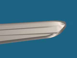
5.2.3.14. Der Distale Schlitten
Wie in Abschnitt 4.6.2 erläutert, definiert die Funktion der distalen Ogive an der Spitze des Holz-Zacher-Schafts mit asymmetrischen medialen und lateralen Parametern den Distalen Schlitten lateral. Dieser Distale Schlitten ermöglicht es dem Operateur, die Schaftspitze nahe der medialen Kortikalis zu positionieren und so eine ausreichende Zementdicke zu gewährleisten. Diese Dicke verteilt die von der Spitze verursachten Spannungen in Richtung der lateralen Kortikalis. Eine Fehlpositionierung des zementierten Schafts in Varusposition wird vermieden.
AD INSERER LA PHOTO TETE SUR ZM 1
5.2.3.14. The Distal Ski
As discussed in Section 4.6.2, the function of the Distal Ogive applied to the tip of the Holz-Zacher stem, with asymmetrical medial and lateral parameters, defines the Distal Skid laterally. This Distal Skid allows the operator to position the tip of the stem close to the medial cortex, thus maintaining sufficient cement thickness. This thickness distributes the stresses caused by the tip toward the lateral cortex. Malposition of the cemented stem in varus position is avoided.
----