5.1.4. Reoperation stems MODULAR Plus
5.1.4.1. System of reoperation of third intention MODULAR Plus
5.1.4.1.1. The MODULAR-Plus stem complete the family of reoperation stems
The majority of the reoperations of hip prostheses made necessary by a noted degradation of anchoring, can be solved with slightly lengthened implants, but whose fixation principle is identical to that of first intention. The typical example is the family SLR Plus compared with family SL Plus.
There are still some cases where the bone, severely damaged by two operations, no longer obtain sufficient anchorage on the proximal half of the femur that can not stand alone, all the constraints of a new implant.
The stems of average reoperation SLR-Plus had already the biggest reasonable length for a rectilinear stem. Any additional length was likely to cause a conflict with the anterior curvature of the femur. To carry out an anchoring deeper than these stems SLR-Plus, the stem was obligatorily to be curved.
I could no longer apply the principle of diaphyseal anchoring with a rectangular section, used for the SL-Plus and SLR-Plus stems, because the preparation of the diaphysis, using overly rigid rasps mounted on a coaxial hammer, was too risky.
The damaged diaphysis is often inapt to receive a short stem whose junction of the impacted conical type exerts too much radial pressure and risk to fissure the diaphysis.
The need for developing a system whose stem at least partly uses a still intact zone of the femoral diaphysis has emerged.
A project of strictly rectilinear extra long stems, like were for example the stems of Wagner, which almost always required to saw into two the proximal part of the diaphysis to allow the rectilinear anchoring zone of the stem to place itself in a distal part of the diaphysi curve, was abandoned.
The MODULAR-Plus system with curved distal stems, proximal parts adjustable in antetorsion on 360°, an original mode of fixation in the cortical bone and a mode of preparation by Spiral Reamer, is a system particularly little traumatic and source of few complications compared with the other methods of deep reoperation. It allows a reconstruction close to the anatomic conditions.
To obtain a sufficient long anchoring zone, I find necessary that this minimum of 10 cm medullary canal, whose bone has a sufficient solidity, is prepared perfectly, presents a conical surface whose curvilinear axis must correspond to the curvature of the stem to implant.
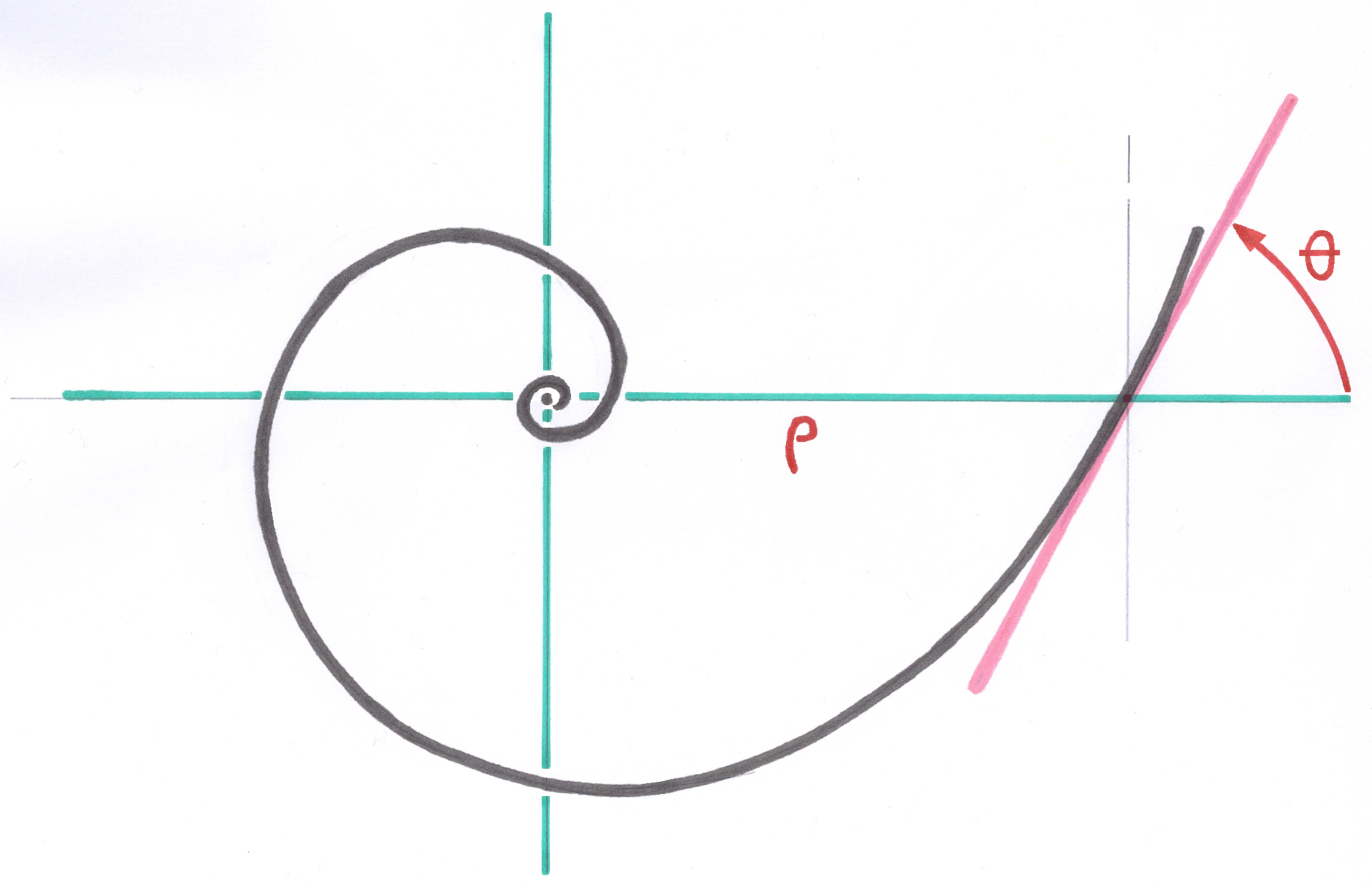
The system of Modular-Plus stems is the result of the application of the principles of Geometric Anchoring to the curved stems in a curved medullary canal ( see Curved Space in Logarithmic Spiral ).
The contact surface presents, as the implantation, of many square millimeters of primary contact with the osseous bed. The balance quickly reached thanks to the incrustation, under prestress, of the 8 edges in the cortical bone of the bearing zone, makes it possible the stem to have, at the end of a few days, a sufficient stability for a partial loading.
This stem being intended for reoperations after two or three failures and the osseous capital being in general strongly reduced, the requirement of the Primary Stability allowing early loading of the patient is not required.
5.1.4.1.2. Limits of application
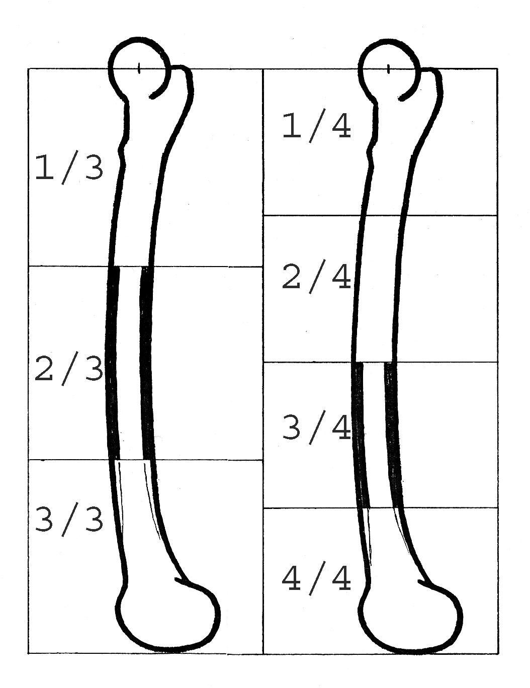
The system of deep reoperation Modular-Plus requires a zone of cortical intact of ten centimetres. So that this length can be perfectly reamed and present a continuous conical zone, it is excluded to consider fixing in the distal third and even less in the distal quarter.
In this area, the femur widens in the shape of a trumpet to the condyles of the knee and cannot obviously be treated by the spiral reamer. Consequently, the Modular-Plus system cannot be regarded as a prosthesis of femoral rebuilding in the event of resection exceeding the middle of the femur.
5.1.4.1.3. Original fixation mode of the stems Modular Plus
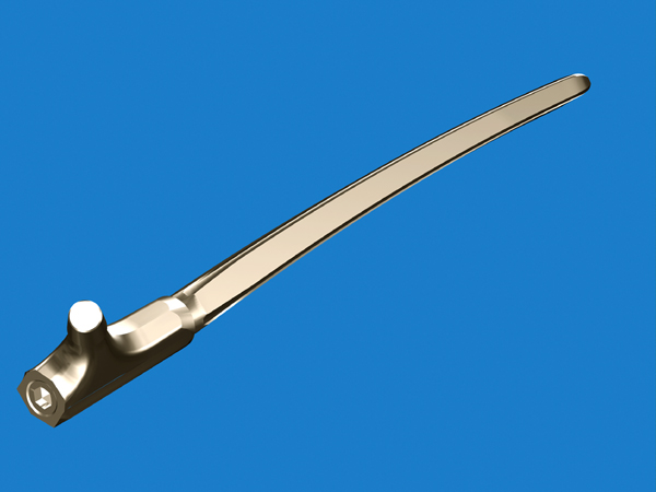
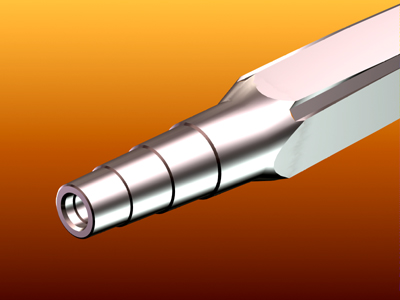
This system comprises a conical junction in the osseous bed with a surface of contact which seems rather low, if one considers only the aspect of the transverse section, but which is actually much more important because the contact takes place over a big length along the 8 sharp edges which are in continuous contact with the osseous bed prepared with precision.
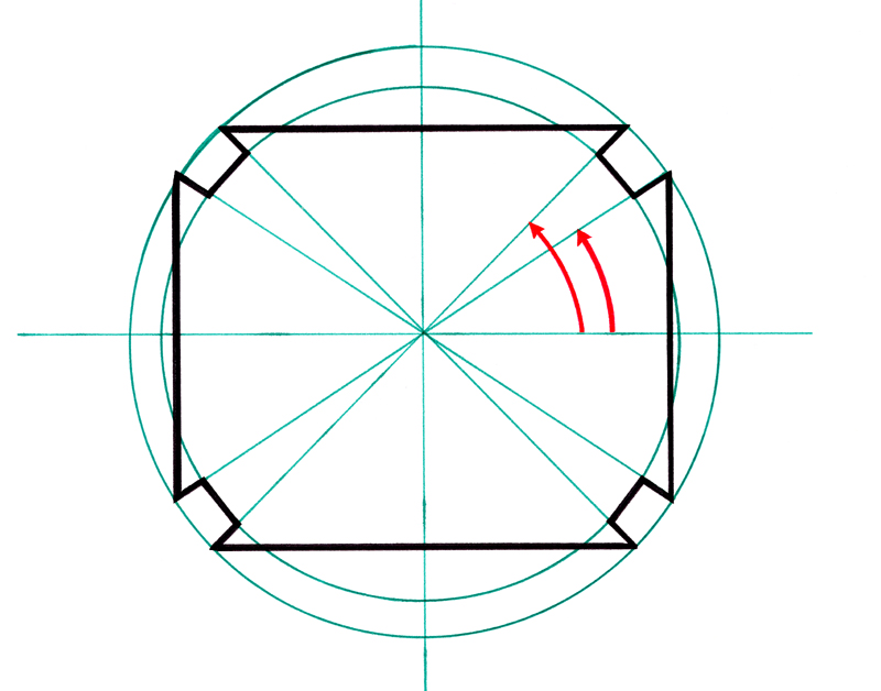
The particular form of the cross section of the stem Modular Plus comprises 8 points laid out on a circle to define the 8 longitudinal edges and 8 other points slightly close to the center of the section to define the grooves milled along the stem. These two families of points are defined in local polar coordinates in the plan of section. The parameters defining these points in the Parameter Base are common to all the cutting sections along the stem.
The internal faces of each groove are parallel to the radii of the circle, and therefore effectively oppose the rotation of the rod after impaction.
5.1.4.1.4. The Ascending Interlocking is a great advantage of the Modular Plus system
The property of the Ascending Interlocking applied to the Modular Plus stems makes it possible to implant the S+1 size in a medullary canal prepared for the size S, without any additional preparation.
The fixation junction which will receive the proximal part is elevated of a predictable quantity. The Total Osseous Length defined by the center of the head will be obtained by the installation of the one of the 2 proximal parts.
If the height change of the fixation junction is excessive, after a reposition test with the shortest test proximal part, a light additional work of reaming is possible to make it possible the stem to go down from a perfectly visible and controllable quantity in order to find the wished intermediate position between the head positioned with the size S and the head positioned with the size S + 1.
All the positions in altitude can be thus obtained with minor corrections.
The observation of the drawing obtained by calculation, in which all sizes are superimposed, shows that a longer third proximal part is not necessary to obtain the desired total length.
I point out that in the case of a heavy reoperation, of third order, the precision of the operation cannot be millimetric any more and some millimetric variations are negligible insofar as the articular tension is envisaged sufficient to avoid too easy luxations. I find preferable to envisage a tension slightly higher than the normal at the time of the reposition.
In my opinion, during a reoperation of this order, the patient should not expect an equal legs better than the centimeter, the priority is left to stability.
I think that a surplus overall length about the centimetre, involving a a little strong articular tension, into postoperative immediate, does not have many consequences, a standardization of the amplitude of the movements will be done by rehabilitation and walk. On the other hand, after an as important reoperation it is not obvious that an insufficient articular tension is corrected naturally.
5.1.4.1.5. Resistance to the rotation of the curved distal anchoring
AD MAKE A DRAWING
A powerful antirotational effect is spontaneously obtained because of installation of a curved stem in an also curved osseous bed. Even in the event of light differences in curves, the assembly has a natural tendency to be oriented so that the two curves correspond.
The flexible spiral reamer creates, in the curved medullary canal, an osseous bed whose curve is in a plan. As the anchoring stem also has a curve registered in a plan, these two plans are directed naturally in the same direction during the insertion of the stem.
In the large majority of the cases, the anterior curvature of the femur is included in FTF plan ( Femur - Tibia - Foot ), (Lexicon, 9.6.1. ). I saw, on rare occasions during operations, the former curvature deviating clearly from this FTF plan. In these cases the continuous adjustment on 360° of the proximal part becomes essential because these variations are not retrievable with latitudes of adjustment by great fixed stages.
In a pathological case with great deformation, it can be necessary to implant the stem with about 90° to FTF plan to obtain a rebuilding with an anatomical antetorsion of the neck.(case of real participation)
Independently from the anterior curvature, the section form of the stem ensures him an excellent antirotatory effect, the 8 interior facets of the 4 grooves, directed in the radial direction being opposed to any rotation as soon as the edges were encrusted with approximately 0,1 mm, like detailed § 5.1.4.2.2.
5.1.4.1.6. Properties of this modular system
The 12 stems have the property of Ascending Interlocking and are followed as if each one of them were an extract of only one and single large curved part.
Thanks to the calculation process of the Optimized Sizes, it was possible to me to remove definitively the need for carrying out several lengths of stems for the same diameter, as in many other modular systems, to reconstitute the desired total osseous length after the osseous bed was prepared.
Thanks to the application of the Principle of Ascending Interlocking, I do not regard the diameter of a stem as the fundamental data for the choice of the size to be implanted.
For me, there is no question to ream cylindrically the femur to 16,18 or 20mm and only then ask the question of the height to which the stem will stop.
My priority is the ideal preparation of the medullary canal to accommodate the required thickness of cortical bone to be preserved intact after reaming, and sufficient length of the bone area which effectively participate in the anchoring of the stem.
The diameters in medium of stem vary approximately from 12 to 25mm and from 10 to 20mm at the point. With only 12 sizes, the finest femurs like the largest will be all prosthesed with an excellent approximation of desired total osseous lengths. However, for patients who are 2m tall, there is a shortage of 1 or 2 sizes , and a reamer corresponding to these 2 sizes.
The preparation by tapered reamer aims to obtaining an osseous bed near to the ideal required by this system without addressing, at the beginning of reaming, the size of stem which will be definitively implanted.
By successive tests of the test stems, the desired total length can be approximate. While continuing to ream, it is always possible to regulate gradually the depression of the stem.
Proximal modules S standard and L long make it possible to obtain all the intermediate lengths. The desired length can thus always be reconstituted with this system.
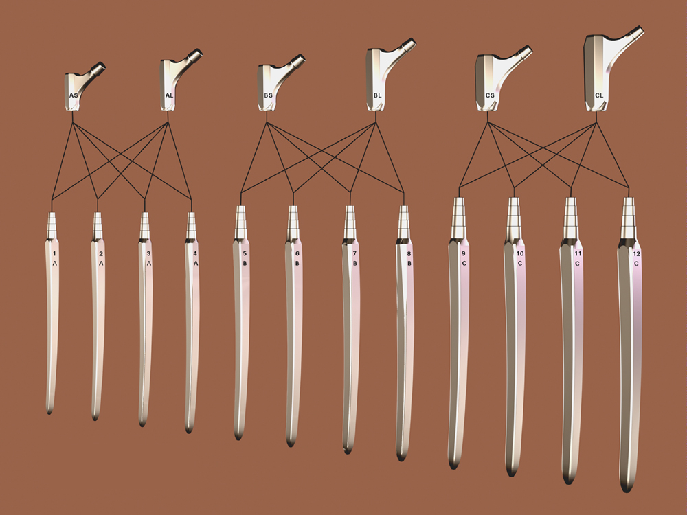
5.1.4.1.7. The Modular Plus system and the three families of junction
The Modular system despite of its restricted number of stems is intended to practically cover all the range of the diameters and lengths of femurs.
I found necessary to create three dimensions of junctions to cover the great variation of the sizes of patients from 1m40 to 2meters, and 30 to 160 kilograms, and the medullary canals whose diameter proximal varies from 12 to 24 mm.
I imposed for the A family a limitation for patients whose weight does not exceed 60 kilograms. The junctions of the families B and C are sufficiently resistant so that there is no limitation of weight.
It is necessary to keep in mind that the anchoring zones of the twelve distal stems are followed regularly independently to the separation of the three families of junction. The lengths of stems and the diameters grow regularly.
With respect to the anchoring principle, the planning and the preparation by conical reamer, the Operator should not worry about the families of junctions A, B and C. He must take account the thickness of safety (6) of cortical bone authorized by taking account of the detailed explanation of the use of the radiological gauges and set up the distal stem of the greatest number.
For this reason the stems were numbered from 1 to 12 without interruption and the families of junctions are subdivided into three groups A B and C compatible with four stems each one.
Inside each family, the proximal parts Standard and Long are common and interchangeable.
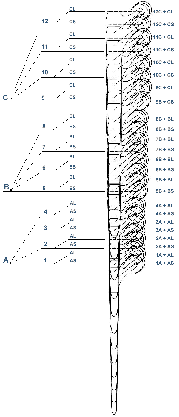
5.1.4.1.8. Interest of the Ascending Interlocking
The Modular system exploits to the maximum the possibilities offered by the Ascending Interlocking. In spite of the need for subdividing the junctions in three families, the system makes it possible to carry out a great regularity in the increase of Total Osseous Lengths. This regularity is highlighted in the chart of the superimposed contours according to the principle of Ascending Interlocking.
5.1.4.1.9. Reliable assembly by the Multicone Junction
I developed a self-locking junction Multicone (R) which gives a mechanical resistance similar to the cast solid implants, confirmed by endurance tests, according to the ISO standards. This junction, with all its components under prestress at large surface, including the conical head of the prestressing screw, takes account of the elastic properties of Titanium and eliminates the micromovements and the wear debris.
It gradually transfers the constraints from a metal part to the other. For an ideal compromise between resistance and volume, 3 families of Multicone junctions define the 3 families of proximal and distal parts.
5.1.4.2. The Distal parts
5.1.4.2.1. The Curvilinear Conical Junction in the bone
Like all the prostheses intended to be fixed in the bone by the principle of Geometrical Anchoring, the system of stems MODULAR Plus respects all the principles of them.
The principle of Geometric Anchoring requires a fixation of the conical junction type between the implant and the bone on a notable proportion of the contact surface. As for all the stems satisfying this principle, the stems of the family MODULAR-Plus seem all extracted from same and single stem which I call “mother-block” and whose each size would be an extract. Of course, this is only one image to explain the principle. Actually, this cutting is obtained by calculation for each size.
The “mother-block”, of which seem to be extracted the Modular stems, satisfied thanks to a new mathematical vision the commonly characteristic properties with the circular cone and the pyramid allowing them to constitute junctions of the conical type.
The “mother-block” Modular is a volume made up in the same way that a cone but around a curvilinear axis extracted from a logarithmic spiral curve and not on a rectilinear axis.
This volume has all the properties of the cone and one of the properties of the logarithmic spiral curves being the conservation of the angles, in each point its surface present with the curvilinear axis a constant angle. To constitute a conical junction, the osseous cavity must be prepared in the shape of a cone with curvilinear axis having the same characteristics. The curvilinear conical junction is thus obtained.
5.1.4.2.2. History of the twinned edges
The comprehension of the stabilization of the incrustation in the bone of the twinned edges of the Modular Plus stem rises by analogy from the method of measurement of the microhardness of materials.
I took note at the time where I dealt with Microscopy in France for Carl Zeiss, of an equipment allowing precise measurement, under microscope, of the hardness of a low-size material.
The principle is the following: under the microscope, one chooses the site of the test then, with an assembly defining the compressive force, one inserts a diamond point in the material. This point is a small diamond cut precisely in the shape of a pyramid at square base and whose edges are with 90°. The value of hardness is calculated after measurement under microscope of dimensions of the pyramidal print left by the diamond.
I observed and I deduced, to carry out of it the logical transposition with an implant in the bone, that the depression of the pyramid stops when the surface of the print sufficiently widened and that a balance is reached.
The principle of this incrustation which ceases automatically when balance is reached led me to conceive the principle of the twinned edges with 90°.
A single edge whose facets would be tilted at 90° would not allow a sufficient antirotatory stability. So that an antirotatory is established, I inserted between the two facets into 90° a groove whose facets in glance are perpendicular to the surface in which this group of twinned edges must be encrusted. In fact the interior facets present a powerful opposition to the rotation and there are the external facets of the edges which ensure the stop of the depression.
If all four twinned edges are distributed on a circle, the interior facets must be directed in a radial way. This principle is described in my consultable Patent in 6.8.5.
The principle of the twinned edges of the Modular stem is different basically from the stems with sharp edges as Wagner stem.
5.1.4.2.3. Geometry of the 8 edges of the Modular stems
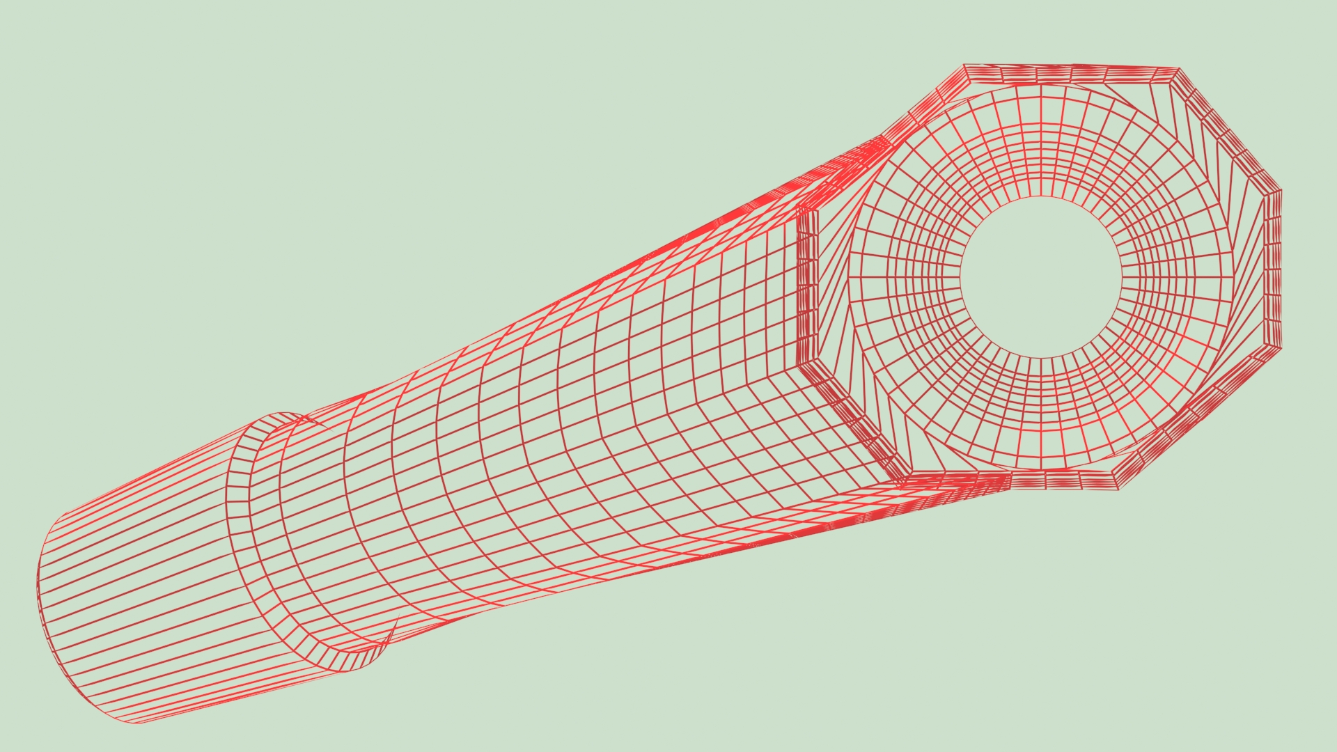
The stems of the Modular system have a slightly rectangular form of section. The flattening is intended to leave a light flexibility, of the order of the millimeter, in the direction of the anterior curvature of the stem. Knowing that the femur also presents a light aptitude for the deformation, the whole of these two flexibilities is useful to compensate for the small differences in curve between the stem and the femur coming from the curve variations of various patients.
Sectional Geometry Despite the rectangular section of the stem, the 8 edges are distributed on a circle to guarantee the simultaneous contact of the 8 points of the section with the perfectly circular preparation obtained by the “Spiral Reamer”. This simultaneous contact takes place on all levels of the stem in the area of active fixation which must extend on 8 to 10 centimeters.
Longitudinal Geometry The 8 edges belong over their entire length to a curved conical form geometrically definite in a Curved Space in Logarithmic Spiral, the only geometry allowing the conservation of the angulation of the cone along a curve. All the points of these 8 edges are supported simultaneously on the prepared osseous surface.
This property is far from being obtained in the assemblies prepared with drills of fixed diameter mounted on a spring axis, because this axis does not establish any geometrical relation between the various levels of the diaphysis during its progression. The axis of such a preparation is sinuous and uncontrolled so that the contact with the implant actually takes place only in some points.
see patent 6.8.5. in appendix.
5.1.4.2.4. The operation of the 8 longitudinal edges
The distal stems of Modular Plus comprise 8 fine edges corresponding exactly, and over a big length, on the osseous surface prepared by the “spiral reamer”.
I had already known about the Wagner deep reoperation prosthesis for several years. Regardless of its lack of curvature which required sawing in two the proximal quarter of the femur, it was known that this stem had a frequent tendency to sink and was slow to osseointegrate.
The preparation of the femur was performed with a rectilinear rigid taper reamer. To my knowledge, the preparation could be approximate without being compelled with a prepared minimal length. In any event, the preparation of a curved channel with a rectilinear reamer cannot bring large rectified surfaces. Wagner hoped much on the incrustation in the walls of the canal of the 8 sharp longitudinal edges to compensate for the geometrical irregularities of the preparation.
INSERER SCHEMA EN COUPE DE LA DISPOSITION EN ETOILE DES 8 ARETES TRANCHANTES DE WAGNER
In the stem of Wagner, the study of functioning of an edge facing the bone shows that the depression is practically not slowed down because of its sharp looks of approximately 12°. The osseous surface which should be opposed to the depression practically does not increase when the edge progresses in-depth. This surface resistant to the depression is not the part already inserted of the surface of the facets but the projection of these surfaces on a level perpendicular to the direction of the depression.
Because of acute angle of 12°, this surface practically does not increase at the time of the successive stages of the depression and does not prevent the depression from continuing.
As long as surfaces in intime contact with the bone are not sufficiently wide the roughness obtained by sanding with corundum does not play a role of immobilization.
Longitudinalement, by Wagner, the angle of each edge with the axis was of 1°, a total angle of the cone of the stem of 2°. Taking into account the angle of 12° of the edges and their conicity, and reamed zone on approximately 100 mm, an incrustation of the edges in the cortical bone of 0,1 mm corresponds to a descent of the stem of 6 mm
Following this phenomenon, 16 mm2 of interface of opposition to the depression of the edges appeared. This surface of opposition is insufficient and the cortical bone of this surface of opposition remains subjected to pressures exceeding the threshold of resorption per excess of constraints. These zones are not any more in the field of Osseous Vitality and the phenomenon of resorption tends to continue.
In the Modular stem, the angulation of the edges is identical, that is to say of 1° compared to the axis. One of the faces of each of the 8 edges being tilted of approximately 45°, the comparison taking place always on a reamed zone of approximately 100 mm, an incrustation of the edges of 0,1 mm, with a descent of the stem of 6 mm creates a surface of opposition of 80 mm2, that is to say 5 times higher than that of the stem of Wagner.
With each additional incrustation of 0,1 mm, the surface of opposition increases by 80 mm2. This rapid increase makes it possible the bone of this surface no more to be in charge beyond the threshold of resorption by excess of constraints.
This depression of the Modular stem makes it possible the bone in contact to be in all points quickly in the field of Osseous Vitality. The Modular stem ceases going down.
For this reason, at the end of the implantation, it is reasonable to envisage a surplus of osseous length from 8 to 10 mm, which corresponds to a light surplus of tension.
It is necessary to envisage, after the implantation of a Modular stem, a discharge of the patient from three to four weeks because the principle of this stem does not get always the normal Primary Stability obtained with stems SL and SLR Plus.
5.1.4.2.5. Study of the anterior curvature
Each size of stem has an anterior curvature corresponding of very close with the real femoral curvatures. Tens of radiological comparisons between templates and radiographies on side enabled me to determine the amplitude of the curves.
I specify that the stems are not defined on arcs of circle and do not have any constant curvature radius. The curve of each stem increases regularly from proximal to distal and follows the shape of a logarithmic spiral curve.
The successive sizes of the series, all being mathematically curved and being extracted from same and single logarithmic spiral curve, have a curvature which evolves regularly of largest with the more small size.
I could check that the correspondence of the curves of the various sizes of stems with the curve of the femurs was excellent for very large patients to the very small patients.
Nevertheless, as for all the logics stated about the implants, these correspondences must be regarded as statistically excellent and that, in some cases, differences may exist. The system of implants must be conceived to present a sufficient tolerance to the variations.
The variations of curves, due to the activity and the lifestyle of the patients during youth, remain in the field where the anchoring stem on the one hand, the femur on the other hand, adapt slightly by their elasticity about the millimeter.
The extreme examples are the femur of a woman, having always had in its youth little physical-activity and a light weight, whose anterior curvature is low, and the femur of a very muscular man and very active in its youth whose anterior curvature is strong.
5.1.4.2.6. Anatomical Proxicurvature on the distal stems
The distal stems of the Modular Plus system have a anterior curvature corresponding of enough close with the anatomy of the medullary canals. Since the proximal parts are symmetrical, I found necessary to include, at the base of the Multicone Junction of the distal part, a slight anterior inclination approaching the prximal form in S of the femur. I called this inclination Proxicurvature.
This inclination, of approximately 3° compared to the curvilinear axis, is relatively low. In a later project ( Ana.Nova ), I increased this inclination to 6°.
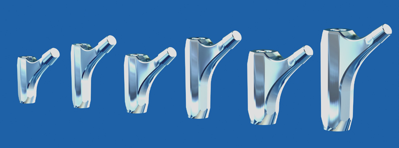
5.1.4.3. The PROXIMAL PARTS
5.1.4.3.1. The proximal parts are left-right symmetrical
A proximal part is adjustable for left or right hip. In this modular system, the proximal part is not really anatomical because the light shift into anterior of the axis of the neck compared to the axis of the proximal third of the femur is not taken into account.
It is only in a later project of modular system, integrating the prostheses of first, second and third intention ( Ana.Nova ), I created anatomical proximal parts lefts and right side with, moreover, variation in lengths of necks.
For reoperations of third intention, it did not seem necessary to me in 1996 to seek an excessive precision, the operations of deep reoperations remainder very difficult and leaving the framework of the anatomically rigorous rebuildings a little.
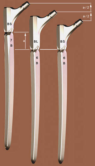
The proximal part is envisaged in 2 heights (standard and long). The long model offers an intermediate total length between 2 successive sizes of distal stem with short neck.
5.1.4.3.2. Graduation of the antetorsion on the proximal parts
Markings indicate standard positions of the antetorsion of the neck, but a fine adjustment and continuous antetorsion is possible after determination of the optimal stability on the manipulation prosthesis.
5.1.4.3.3. Mathematical models applied to the proximal parts
The curves of transition between the top from the neck and the direction of the main axis, i.e. the Curve of the Calcar, were obtained by an approximation of the orientation in each point of the curve taken naturally by the osseous trabecula inside the spongy bone of the neck and by the calcar itself. Also, the intertrochanterian curve in each point is obtained by this modeling.
5.1.4.3.4. Antetorsion of the neck chosen with 20°
It is well-known that compared to a standard position of the femur the axis of the femur neck of the patients seems to be tilted of approximately 15° forwards. After an attentive anatomical observation, I noticed that the natural axis of the collar did not meet exactly the curvilinear axis of the femur as let it imagine radiographies of face. At the base of the neck, these two axes are at a distance from 6 to 8 mm.
For the proximal parts of the Modular system whose symmetry was decided to decrease the number of components, I preferred to incorporate this sagittal shift of the head of approximately 6mm in the initial antetorsion of the proximal part. For this reason the initial antetorsion was carried to 20° compared to the reference mark of standard positioning engraved on the proximal parts.
This way, the proximal part, implanted in a left femur or a right femur, is directed with 20° each side when the engraved reference mark is in position 0 compared to the distal stem.
What is essential for me it is that the positioning of the center of the head is close to its natural three-dimensional position. This position of the head is for me priority compared to the angle visually observed of the metal part of the neck.
5.1.4.3.5. Graduation of the antetorsion settings
The Multicone Junction allows an uninterrupted orientation on 360° of the antetorsion of the proximal part on the distal stem. It is exceptional to be obliged to adjust the antetorsion on more than 20 degrees compared to the initial position of the proximale part whose collar is already with 20°. On both sides of engraving locating the standard position, I calculated markings with - 20°, - 10°, 0°, + 10°, + 20°. That makes it possible to locate during the assembly and of impaction before the implantation the orientations in antetorsion from 0° to 40°. In exceptional cases, of great deformation, any other adjustment remains possible.
5.1.4.3.6. Octogonal section of the proximal parts with head on 20° on both sides
It is natural to be convinced that a proximal part of octogonal section obtains a rotation stability thereafter or in torsion much better than if this part were round or oval, this does not make any problem.
The choice of the inclination of 20 degrees of the facets of the proximal part allows an evaluation of the antetorsion on the postoperative radio because in the standard position in position with 20 degrees of antetorsion of the neck, the profile on radiography, if the stem is of face and profile, is perfectly controllable and one realizes that the proximal part is well directed with 20 degrees.
AD MAKE A DIAGRAM
5.1.4.3.7. The Calcar Curves by the method of missile shootings
On the proximal parts of the Modular stem, the description of the surface located under the neck and connecting the body of the proximal part to the cone of junction receiving the spherical head, is obtained by a family of 24 curves. I developed the definition of these curves by having with the spirit the simulation of the orientation of the crystalline components of the cortical bone and the trabeculae of the spongy bone inside the neck in the vicinity of the cortical.
They are typically curves of transition as evoked to paragraph 3.6.2. Each curve connects, by stages of inclination calculated successively, a segment close to the vertical of the body to a corresponding segment of the ring located under the base of the cone. The curves in “missile” leave tangentially and arrive tangentially at these segments. As the proximal part of this prosthesis is left-right symmetrical, each curve is described in a vertical plan.
5.1.4.3.8. Intertrochanterian curvs
The Intertrochanterian surface located at the top of the neck and connecting the top of the proximal part to the high part of the ring to the base of the cone is defined in a similar way. On the other hand, it is about an approximation of the direction of the forces of traction being exerted on material during alternate loadings.
5.1.4.3.9. Uselessness of a third length of proximal parts
I heard several times requests concerning proximal parts higher than the long version of each family of junction of the Modular system.
These requests come from the practice to lay out, in concurrential systems, of a greater number of proximal parts. This variety was necessary because the position in height could not be dominated methodically. The desired total osseous length could not be defined before its final adoption by wedging. The position in height of the distal stems was not defined by the preparation by reaming or drilling.
Contrary to that, in the Modular Plus system, the principle of Ascending Interlocking and the perfectly conical preparation with the spiral reamer allow to obtain with a sufficient precision any desired position of the stem. The two heights of proximal parts make it possible to compensate for per half the height variation obtained between two consecutive sizes of stems, as presented § 5.1.4.1.8.
In the Modular system, it is always necessary to choose the biggest possible size of distal stem and not to seek to compensate with a higher proximal part.
From the point of view of the risks a possible part proximale higher height would statistically present a higher risk of fracture of junction.
The overhang caused by a larger distance between the center of the head and the base of the junction between the distal stem and the proximal part, and the extension of the lever arm cause more constraints on the junction. Taking into account this additional risk, I disadvise strongly the use of extra long proximal parts.
If, in addition to that, the operator uses heads with extra long neck whereas it has heads with long neck, in which the increase in risks is negligible, it again increases in an unacceptable way the constraint on the junction. There is an useless competition with the more reliable solution obtained by establishing a distal stem of higher size.
Naturally, as for any implantation with Ascending Interlocking, it is possible to readjust, all the intermediate positions between a prepared size and the following size, the total osseous length by carrying out some additional turns with the Spiral Reamer to descend the stem from a few millimeters and to obtain thus the osseous overall length nearest to the ideal for this patient.
5.1.4.3.10. Role of the prestressing screw with conical head
The prestressing screw is an important complement of reliability of the junction between the distal and proximal parts of the Modular system.
Its principle is independent of the Multicone or monocone technology of this junction. The principal function of the screw is to carry out in a permanent way a traction tightening the conical junction. After tightening of the screw, the three parts distal, proximal and the screw itself are put in prestressing. Any tendency to an axial separation and micromovements is excluded.
The conical shape of the head of the screw is intended to prevent any tendency to loosening thanks to the large surface of support between the parts and the exerted axial pressure.
A traditional tightening screw which would rest on a flat seat would have much less support surface and could probably undergo horizontal micro-movements in relation to its support seat, because it must be imagined that the entire assembly will be in permanently subjected to powerful alternating flexions.
The conical head of the prestressing screw permanently prevents horizontal micro-movements during bending.
5.1.4.3.11. Uselessness and risks of XL and XXL heads
I remind you that the Modular system was designed for prosthetic heads available with 3 neck lengths only, short neck, medium neck and long neck. The differences in total bone length are of the order of 4 millimeters maximum. If you want greater compensation to adjust the total bone length, you must proceed as in the previous paragraph and absolutely avoid the use of XL heads with extra long necks and especially XXL.
These heads, most of the time made of metallic material and not ceramic, have a tubular skirt which allows them to obtain the additional length.
This skirt which moves the junction cone outside the head itself has a diameter greater than the diameter of the neck originally provided at the base of the cone 14. This greater diameter causes a significant reduction in the amplitude of pivoting, of the order of 10 degrees in all directions and risks having a leverage effect by coming into contact with the edge of the spherical hollow part of the acetabulum.
The risk of dislocation is clearly increased and in any case the risk of permanent impingement with abrasion of the polyethylene is also aggravated.
I remind you that I made a proposal to AFNOR and CEN, for a European standard to practically prohibit the use of heads with skirts and to reserve this solution only for extreme cases occurring during operation for other reasons and otherwise insoluble. (Doc 6.7.2., page 18, § 3.2.2.)
5.1.4.4.1. The Modular prosthesis should not be used as spinal nailing
Following cases of subsidence that I was informed of and observation of the corresponding radiographs, it appeared that the Modular stem had been implanted as an intramedullary nail, with the implanted size being three sizes smaller than the ideal size for this femur. Obviously, the Operator had not taken into account the information on the planning and operating technique of this system.
Modular stems are fundamentally different from cylindrical stems or nailings.
The particular profile comprising the 8 edges requires preparation over a sufficient length and must, under no circumstances, maintain mobility all along the medullary canal.
5.1.4.4.2. Is a lock possible?
I have been asked several times to provide anchor stems for the Modular prosthesis with one or more holes intended to receive transverse locking screws. These demands are almost incompatible with the principle of anchoring by conical junction of this system which must present primary immobility but not necessarily true Primary Stability. It is necessary for the stem to come to a permanent stop, that it is not prevented from descending approximately 1 cm so that the surfaces in square millimeters in intimate contact between the stem and the prepared canal reach their equilibrium value. .
At the time, I proposed the possibility of a series of stems allowing locking. These stems should no longer have the 8 longitudinal edges. The latter had to be replaced by 4 chamfers at approximately 45° defined exactly by the 8 edges and the filling of the grooves, the exterior geometry remaining unchanged.
A nailing or locking stem is never completely still, and there is always some play between the hole and the locking screw. The stem must not present any aggressive geometry facing the bone. The version with 4 flat chamfers was therefore possible.
5.1.4.4.3. Missing intermediate length family
The decision was made at the beginning of the Modular project to solve the most extreme difficulties first and to deal with an intermediate depth range a little later, because the change in depth between the Modular stems and the SLR stems More is important.
Subsequently, there was talk of producing a series only shortened by three centimeters on average. Indeed, the length of the Modular stems may seem large for reoperations for which the SLR is only a little insufficient. For these intermediate cases, the use of a stem whose total angulation is 2° is not ideal and I recommended an angulation of 2.8° precisely intermediate between the angulation of the Modular and the SLR. This angulation would allow a doubling of the resistance to depression.
This option requires a series of 2.8° reamers instead of the 2° of the long series.
5.1.4.5. PREPARATION OF THE FEMUR BY REAMING
The preparation of the femur is carried out with the flexible conical Spiral Reamer. It is necessary to have 10 cm of femoral diaphysis, the thickness and solidity of which will allow sufficient preparation.
It is possible to produce, with this instrument, a perfectly conical curved cavity intended for self-locking and presenting a regular curvature, in a single plane, much better controlled than with instruments mounted on a flexible axis.
The instrument, thanks to a rounded olive-shaped tip, is oriented by the curvature of the cortex, and cannot cause an exit.
The inverse direction of the spiral avoids any blocking in normal rotation and cutting only takes place if the operator presses hard. As soon as the pressure stops, the instrument moves back by itself. The reamer must go in 10cm after starting work to obtain 10cm of conical fixation area.
As much as possible, try to preserve part of the proximal femur, to complete the distal anchoring and immobilize the proximal part.
This modular system, with 12 distal stems and 6 proximal modules, allows, taking into account the Left/Right inversion, to constitute 48 different prostheses, practically tailor-made and adapted to the anatomy.
5.1.4.6. OPERATIVE TECHNIQUE ADDITIONS
The following articles are in no way intended to replace the operating technique brochures provided by the manufacturer and approved by Professor Zweymüller. It is normal that these brochures, which would then have been too cumbersome, do not deal in detail with all the tips and reflections which may have appeared during the design of the system and sometimes during clinical experiments.
5.1.4.6.1. Radiological determination of the diameter of the old head
It is very useful, before a reoperation, to know with a good probability the diameter of the head in place. It is rare that information on the diameter of the head and more generally on the model and size of the prosthesis is known to the patient or available in their file.
I created a radiological template for determining head diameters TO BE COMPLETED
INSERER GABARIT DES TETES
CONSEILS D'USAGE DES GABARITS
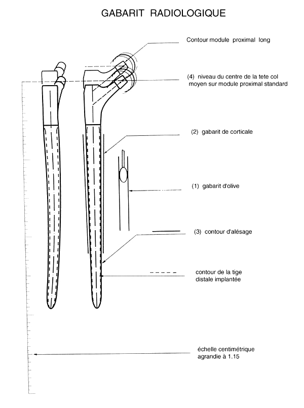
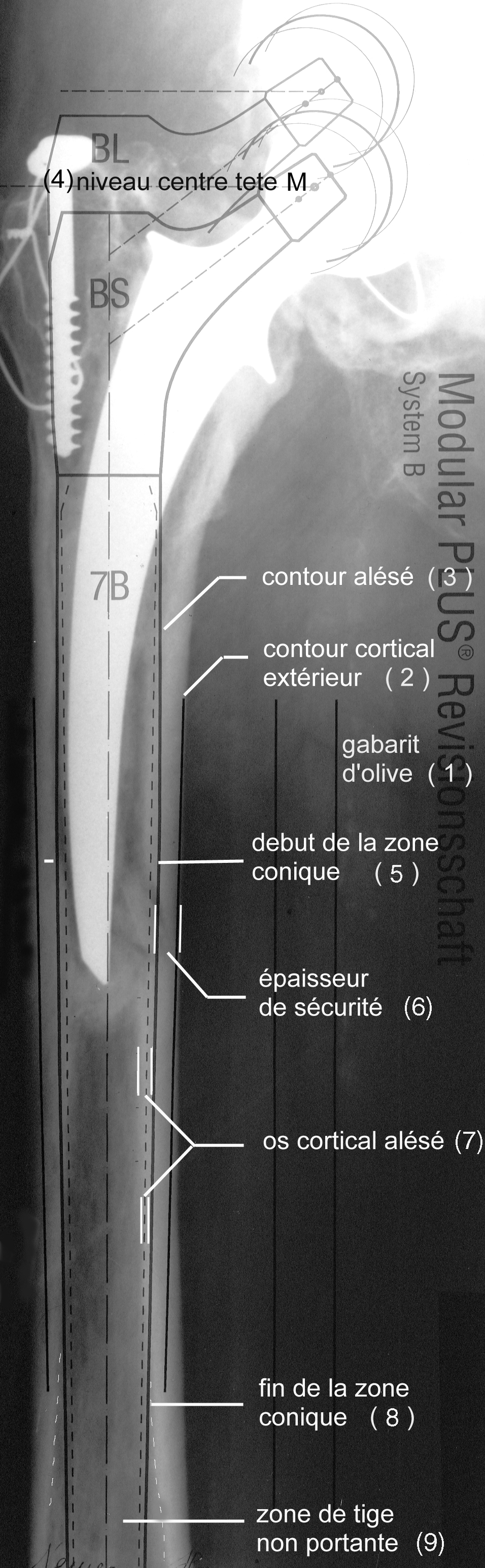
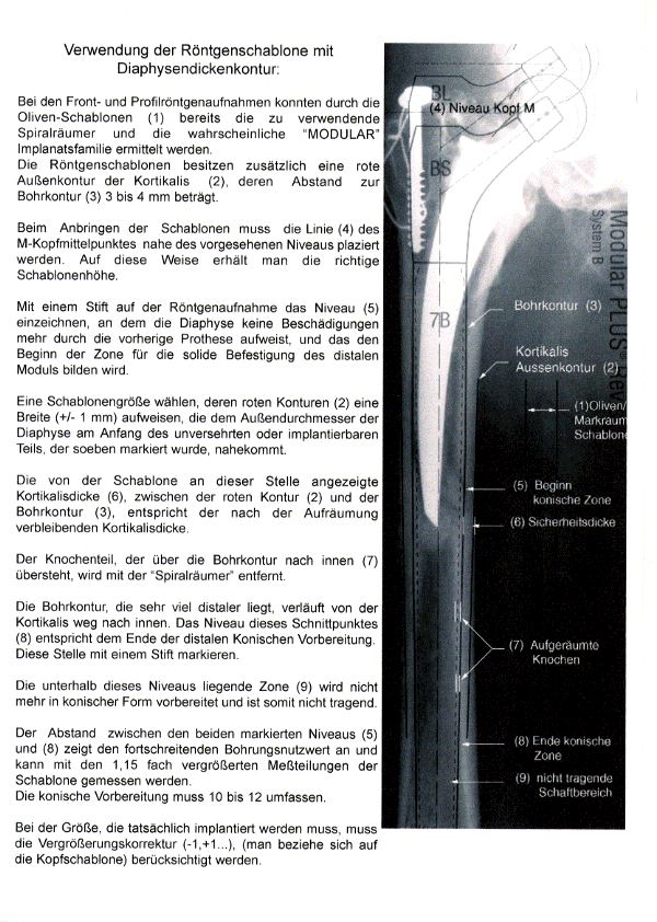
Using the X-ray template with diaphyseal thickness contour
During the front and profile X-rays, the size of the first spiral reamer to be used and the likely “MODULAR” implant family could be determined using the olive templates (1). The X-ray templates also have an outer contour of the cortex (2), the distance from the drilling contour (3) is 3 to 4 mm.
When attaching the templates, the line (4) of the M (medium) head center must be placed close to the intended level. This way you get the correct stencil height.
Using a pencil, mark on the radiograph the level (5) at which the diaphysis no longer shows any damage from the previous prosthesis and which will form the beginning of the zone for the solid attachment of the distal module.
Select a template size whose red contours (2) have a width (+/- 1 mm) that is close to the outer diameter of the diaphysis at the beginning of the intact or implantable part that was just marked.
The cortical thickness indicated by the template at this point (6), between the red contour (2) and the drill contour (3), corresponds to the cortical thickness remaining after the cleanup.
The part of the bone that protrudes inwards beyond the drill contour (7) is removed with the Spiral Reamer.
The drilling contour, which is much more distal, runs inward away from the cortex. The level of this intersection (8) corresponds to the end of the distal conical preparation. Mark this spot with a pen.
The zone (9) below this level is no longer prepared in a conical shape and is therefore not load-bearing.
The distance between the two marked levels (5) and (8) indicates the length of the conical bore and can be measured with the 1.15x magnified measuring graduations of the template. The tapered preparation must be 10 to 12 centimeter long.( 4 to 5 inches)
The size that actually needs to be implanted takes into account the magnification correction (-1,+1...), (refer to the head template).
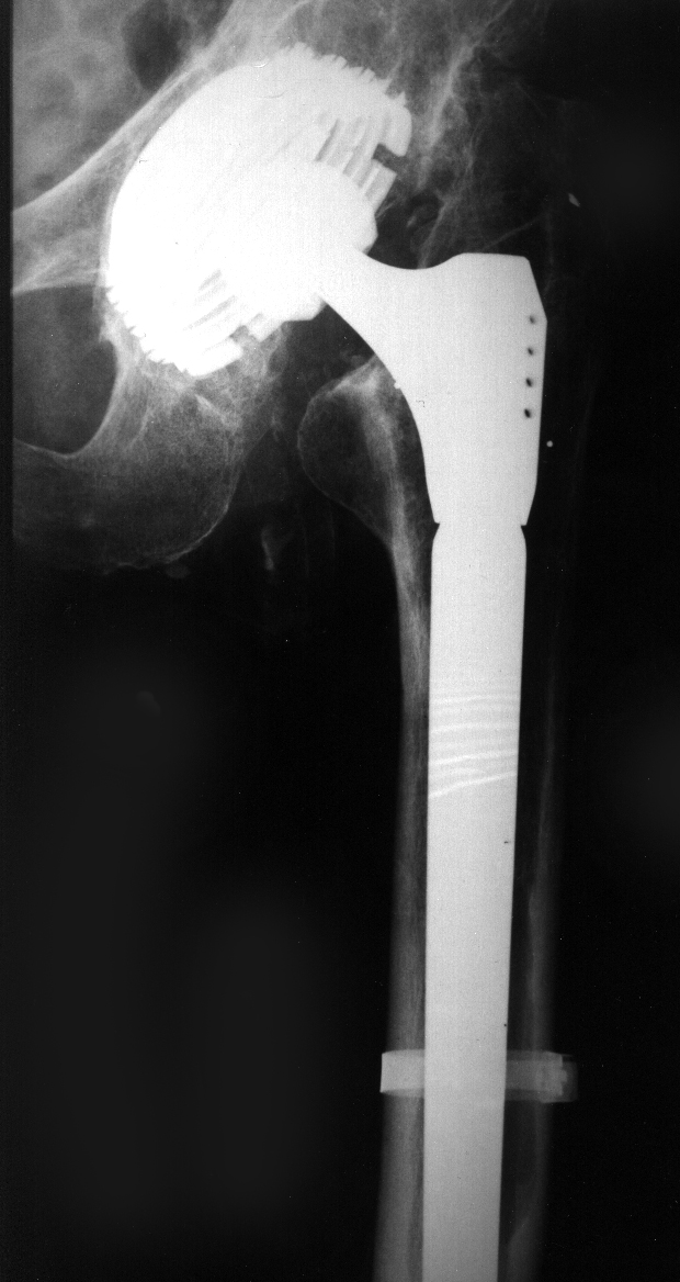
INSERT RADIO WITH TEMPLATE
INSERT DRAWING TEMPLATE EXPLANATION
INSERT PHOTO OF 4 BLUE REAMERS
REAMER TECHNOLOGY (ANGLES...)
For such a deep reoperation, it seemed necessary to me to abandon traditional rasps for the preparation of the bone bed. I have not found an acceptable compromise between the number of rasp teeth (4.4.5.) allowing chips to be removed over such a great length, and the permanent risk that shocks would cause in an already largely damaged femur, necessary to detach hundreds of chips simultaneously. I therefore had to develop a method and an instrument for rectifying the bone bed without violent impaction.
The discovery of the flexible Spiral Reamer allowed me to resolve this requirement for a non-traumatic preparation.
Depth markings on the axle and size selection.
Ring-shaped depth marks are placed on the handle of each reamer and indicate the level that will be reached from the top of the corresponding standard proximal part. The position of these rings is exact because the reamers and their handles are calculated at the same time and by the same program as the distal rods.
The reamer therefore constitutes, during preparation, a first trial prosthesis and makes it possible to read what size rod will be implanted.
The Impact Reserve is taken into account in the spiral reamer. TO DEVELOP*
Reamers in families of 2 TO BE DEVELOPED
Technical advice for the reamer. TO BE DEVELOPED
User communication, proposals for creating commented examples. TO BE DEVELOPED
AD make independent paragraph for mathematical principle.
----
Next stems: stems ANAtomicGEOmetric, project