
3.5. The Curved Space in Logarithmic Spiral
3.5.1. Summary
With an aim of developing curved implants incorporating itself better than rectilinear stems in curved diaphyses, but which satisfy all the principles of Geometrical Anchoring, I carried out a mathematical study arriving at a single conclusion: only stems calculated in a Curved Space in Logarithmic Spiral can meet this requirement.
Having no former source, I developed a new mathematical method to describe these implants.
Two families of curved femoral stems were designed in Curved Spaces in Logarithmic spiral: The Modular Plus stems for deep reoperation, and the family of the stems of the Anatomica.Nova ( Ana.Nova) project covering all the ranges: of first intention, of reoperation and deep reoperation.
In addition, I pushed the development further for the design of the “Inverse Spiral Reamer” which is used to implant the curved stems as deep reoperation with geometrical anchoring Modular Plus. The description of this highly original instrument will be developed further.
3.5.2. Geometrical Anchoring and curved implants
Implants having all the properties of Geometrical Anchoring seemed to be able to be realized only with rectilinear main axes. By asking me the question: is it possible to satisfy the conditions of Geometrical Anchoring with curved stems, I arrived at the following observations:
3.5.3. The curvilinear axis in arc of circle is unsuited to Geometric Anchoring
An implant, whose curvilinear axis and contours would be portions of circles, never satisfies mathematically the principles of Geometric Anchoring. Any attempt to create an implant with a circular curvilinear axis would involve too rough approximations. The Principle of the Conical Junction in the bone would not be satisfied.
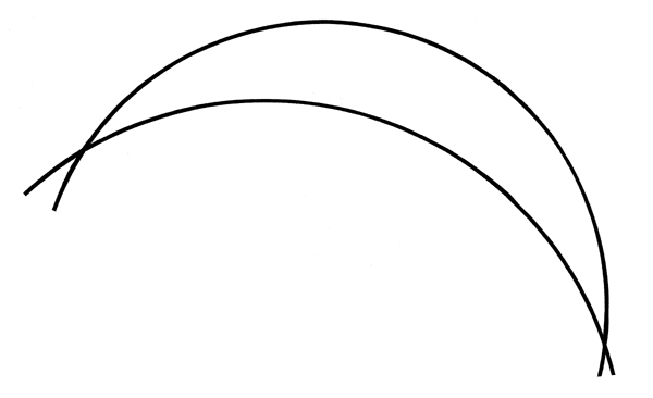
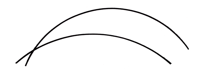
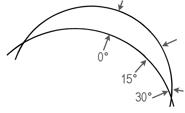
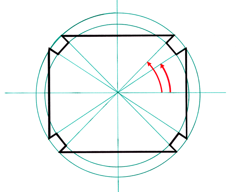
If one tries to schematize a conical junction of circular curvilinear axis by representing the contour of the stem by two arcs of circle ( which present two points of intersection), one sees in an obvious way that the angle of the tangents in two points face to face on the two circles does not remain constant in any area of these circles.
At the two points of intersection, this angle is maximum whereas, if one moves away from a point of intersection, the circles become gradually parallel and end even up meeting at the second point of intersection. It is imagined easily that the addition of the third dimension to this diagrammatic geometry will not more make it possible to carry out any curved conical junction.
3.5.4. The Logarithmic Spiral
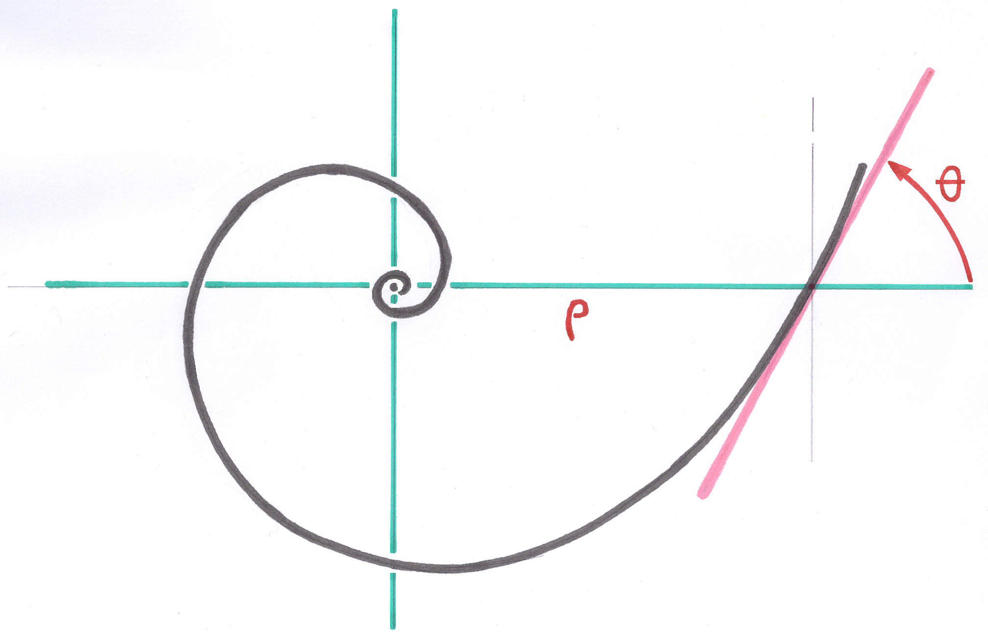
To my knowledge, this problem has a unique mathematical solution. This solution is brought by the Logarithmic Spiral curve which has the property to present, all along the curve, a constant angle between the tangent in a point of the spiral and the radius-vector connecting this point to the Asymptotic Pole of this spiral.
The multiple more or less rough graphic approximations of the spirals, using successive and increasing arcs of circle, and that one finds in all the articles of the Literature and on Internet under the word Spiral and even Logarithmic Spiral curve, are only suitable for decoration, but not scientifically to create curved implants and conical junctions.
I must pay tribute to Mr. Dupin, my Professor of Special Mathematics, who gave me this understanding but also the ability to generalize.
3.5.5. The Logarithmic Spiral space to 3 dimensions.
Remembering the remarkable property of the logarithmic spiral curves of conservation of the angles but not having found anything in the books about the extensions of the logarithmic spiral curve to the third dimension, I had to develop the methods, the formulations and finally the transposition in data-processing language, to be able to apply rigorously, without roundings and smoothings, the properties of the logarithmic spiral curve to the curved three-dimensional prosthetic stems.
I called “ Curved Space in Logarithmic Spiral ” the global geometry in which all the points of the implant are calculated. In order to be able to transmit these points to manufacture on digital machines, I return to the traditional geometry by projecting each one of these points in the Euclidean orthonormed space.
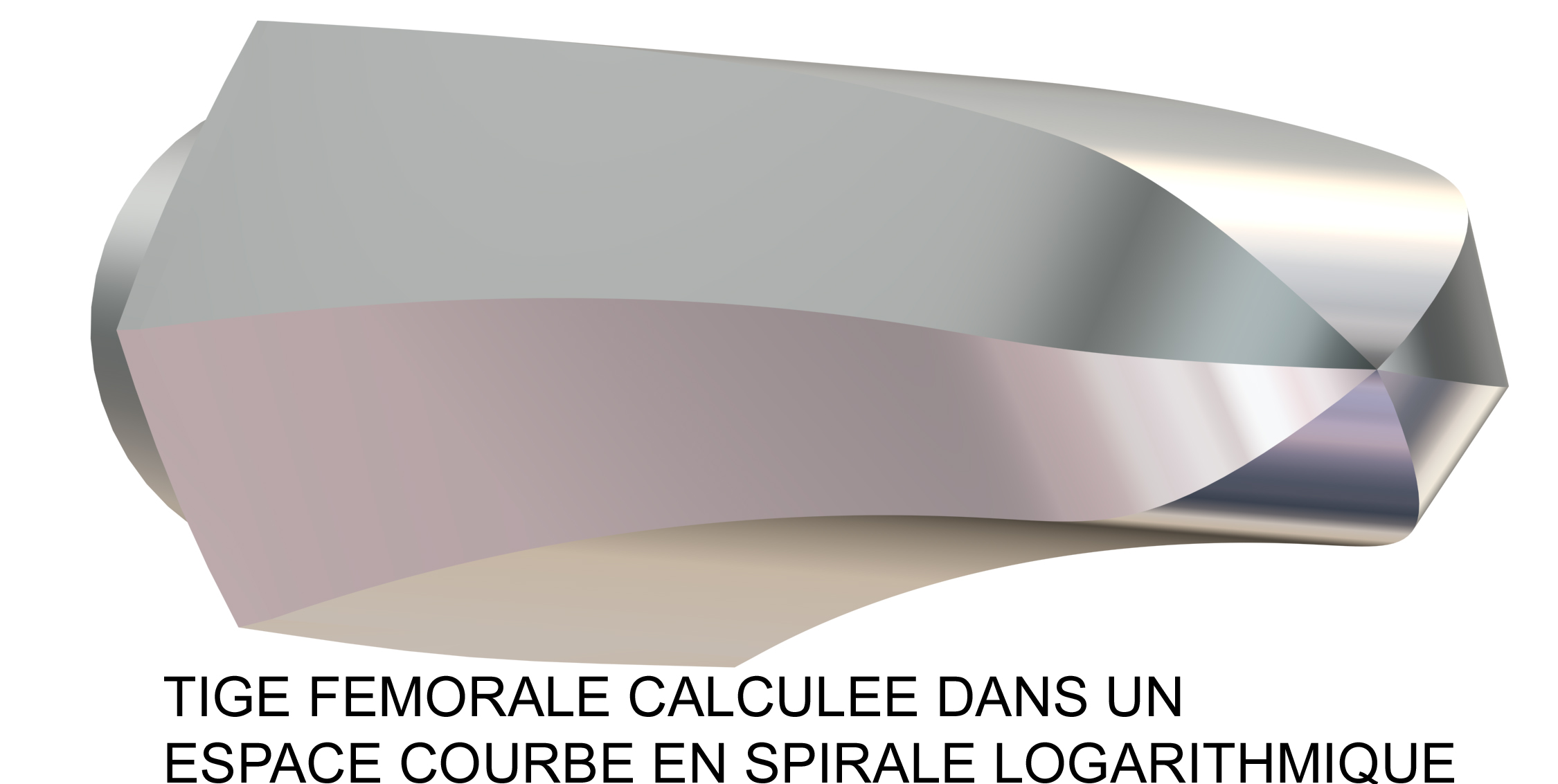
It was then that I noticed that most molluscs, snails, mussels and others are described in a Spiral Logarithmic space, as are galaxies, despite some disturbances.
Only an implant described in a curved space in logarithmic spiral can have the property of curved conical junction. All the curved implants which are not calculated with this geometry are incompatible with Geometric Anchoring.
I developed two groups of application of the logarithmic spiral curve:
3.5.6. The group of the stems
The first, whose curvilinear axis is in a plan.
This curvilinear axis is used as reference to each level of cutting along the axis, has a local orthonormed space in which all the points belonging to this level are defined. The edges of the stems intended to come in contact with the osseous walls prepared by rasping or spiral reaming are also logarithmic spiral curves, in 3 dimensions, moving away regularly from the curvilinear axis and forming constant angles with this axis. It is this first group which is at the base of the various families of curved stems that I had the opportunity to develop.
3.5.7. The group of the reamers
The second group has a three-dimensional curvilinear axis with multiple whorls, described in a space in which the coordinates in Z of the points resulting from the cutting are themselves distributed according to a logarithmic function. It is this group of curved spaces which enabled me to develop the “Inverse Spiral Reamer” intended to replace the rasps for the implantation of the stems for deep reoperation Modular Plus.
In appendix 9.8.7. full text of my patent EP 0.788.772. of the 08.02.1996
3.5.8. Discretization of the curvilinear axis
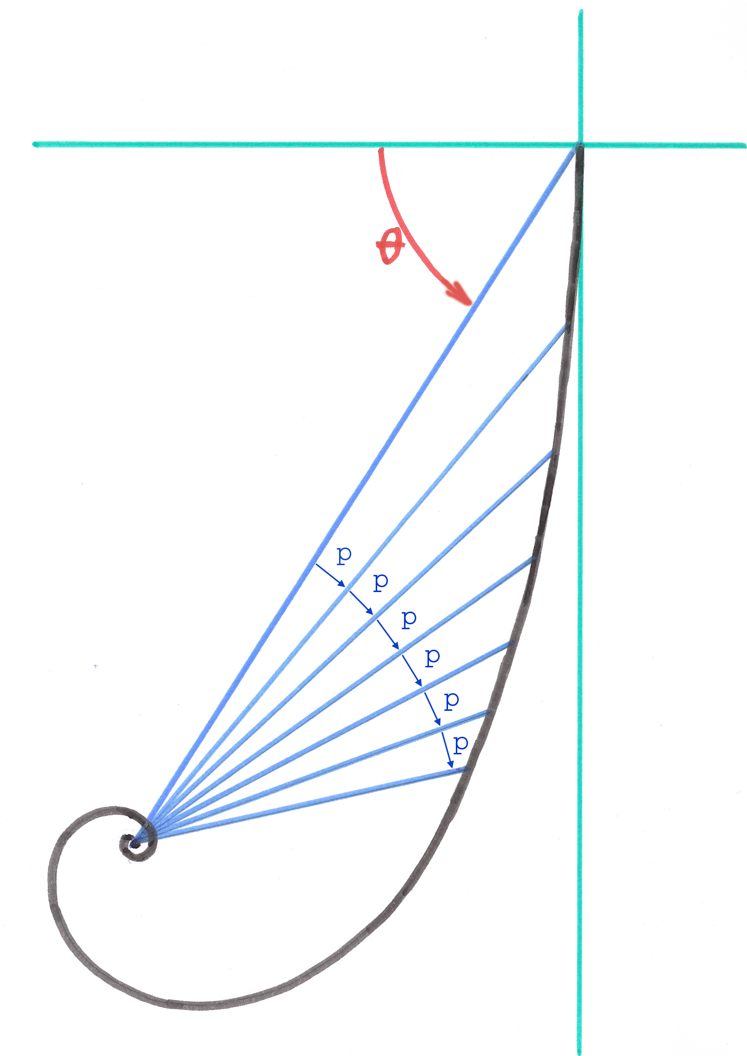
The cutting of these curves along the curvilinear axes does not take place linearly, but by constant angular steps carried out by the radius-vector coming from the pole of the spiral and meeting the curvilinear axis.
The total curvature of the curved implants calculated by this method must be limited to approximately 0,2 radian.
3.5.9. Description of an object in a curved space in logarithmic spiral
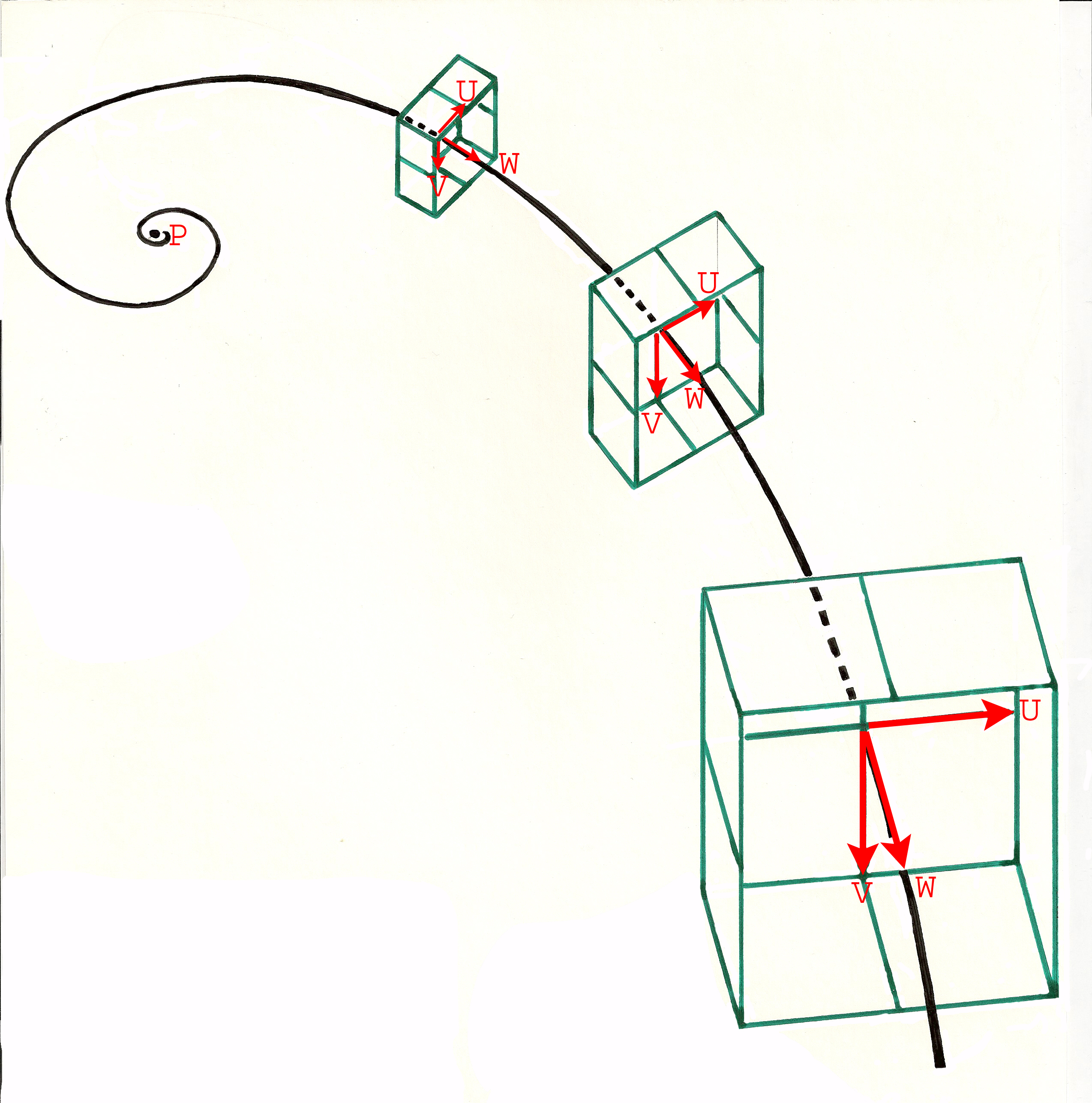
In each point of the nonlinear cutting of the curvilinear axis is defined a local vector space, orthonormed or not, but whose two vectors U and V are in the perpendicular plan to the axis and are controlled by the vector W defined by two consecutive points on the curvilinear axis. Thanks to the remarkable properties which rise from the logarithmic spiral , all the local vector spaces, thus defined, are homothetic.
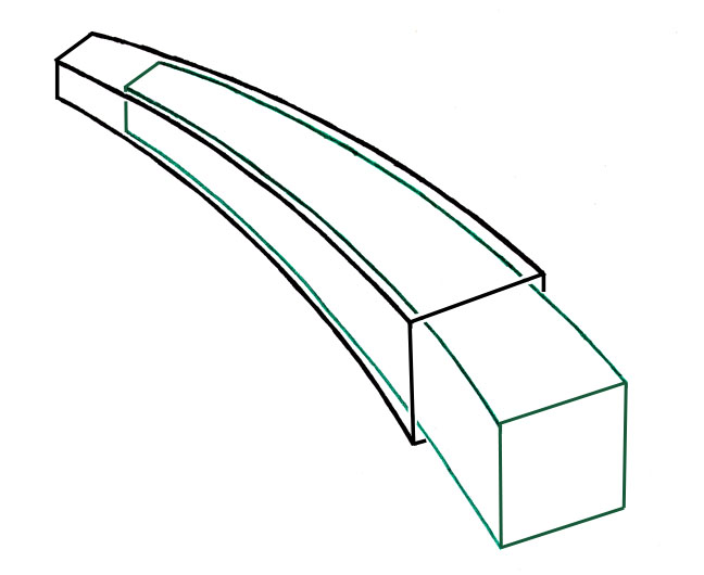
All the elements of object described in these local spaces by identical sets of coordinates are similar, their proportions and especially their angles are identical. In the case of the Modular Plus stems, they are the cross sections of rectangular form and the 4 grooves which are defined in the local plans U and V. These vectors U and V are defined like perpendiculars with the local vector W, defined by two consecutive points of the cutting on the spiral axis, and their norms are identical. On the other hand, the norm of the vector W depends on the interval of cutting along the axis, this cutting not being linear but with logarithmic intervals. These intervals are obtained by the intersections of the axis spiral with radius-vectors resulting from the pole progressing by constant Angular Steps which are defined by a parameter.
3.5.10. Stems implanted in a curved conical medullary canal
If the local section of the stem has a symmetry of revolution, or if the all points of the cross section which are pressed on the bone are laid out on a circle, as in the Modular stem, it is very effective and powerful to define the points of the drawing of the section in local polar coordinates in each plan of section. The parameters defining these points in the Base of Parameters are common to all the sections of cutting along the stem.
When the points of the section in progress are calculated in their local space, they are then projected in the millimetric orthonormed general space intended to feed the programmes of numerical manufacture. The angles used for this projection are those obtained starting from the orientation of the local vector W delimited by two consecutive points of the cutting of the curvilinear axis.
----