5.3.1. Cups BICON Plus
5.3.1.1. History of the Bicon Plus Cup Design
The Bicon cup is naturally a successor to the screw-retained Zweymüller monoconical titanium cup from AlloPro.
Since the use of solid polyethylene Endler cups, the acetabulum preparation for the AlloPro monoconical cup has been performed with conical burrs with a sharp, unrounded front edge. This edge, already used for the 1979 and 1980 Endler cups, was too aggressive given the size and shape of the burrs, which were somewhat different from the cups themselves.
Even then, it was possible for the bottom of the acetabulum to be perforated and a moon-shaped slit to be visible at the bottom. This meant that the preparation of the acetabulum, even before tapping for the Endler acetabulum, was excessive.
5.3.1.2. Observations and Experience on the Grading of Previous Cup Sizes
Since 1981, I had observed a very poor distribution of Endler cup sizes. At that time, I wrote a proposal for modification, along with a description of the procedure to be applied. For some patients, the operator was forced to choose an implant that was too large when an intermediate cup would have been perfectly suitable. However, the available smaller size burr was too small to reach the edges of the acetabulum and did not allow for a sufficiently deep tapping.
5.3.1.3. The monoconical titanium shell
Subsequently, in 1986, the Zweymüller AlloPro monoconical acetabular cup was developed. Also for this cup, the truncated cone-shaped milling was excessive, with very sharp angles. Again, during preparation, the acetabular base was almost always perforated.
Following these observations during surgery, I noted that the titanium thickness at the shoulder of the AlloPro screw-retained cups allowed for a chamfer of several millimeters while maintaining sufficient titanium thickness.
I also noticed, while preparing a prototype from an existing cup with a chamfered shoulder, that the elasticity and strength of the shell were in no way affected by this modification.
This prototype was created to study the feasibility of a similar shell required by a very young patient of Professor Touzet at Necker Hospital in Paris.

5.3.1.4. The oblique frontal "bicone" of the shell
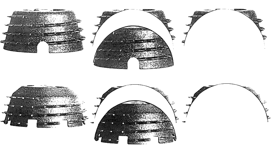
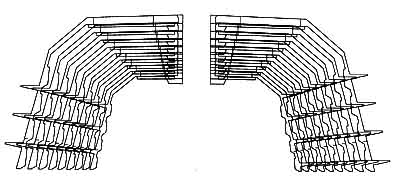
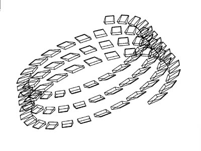
While preparing a presentation in 1999 for the 20th anniversary of Zweymüller prostheses in Vienna, I drew explanatory diagrams demonstrating that the Bicon shell preparation was an excellent approximation of the natural shape of the acetabulum with very little additional bone loss compared to a spherical preparation. The broken-line contour exhibits excellent resistance to tilting when compared to a spherical shell in a spherical cavity.
5.3.1.5. Design of the Bicon Cup Inspired by a Real-Life Case
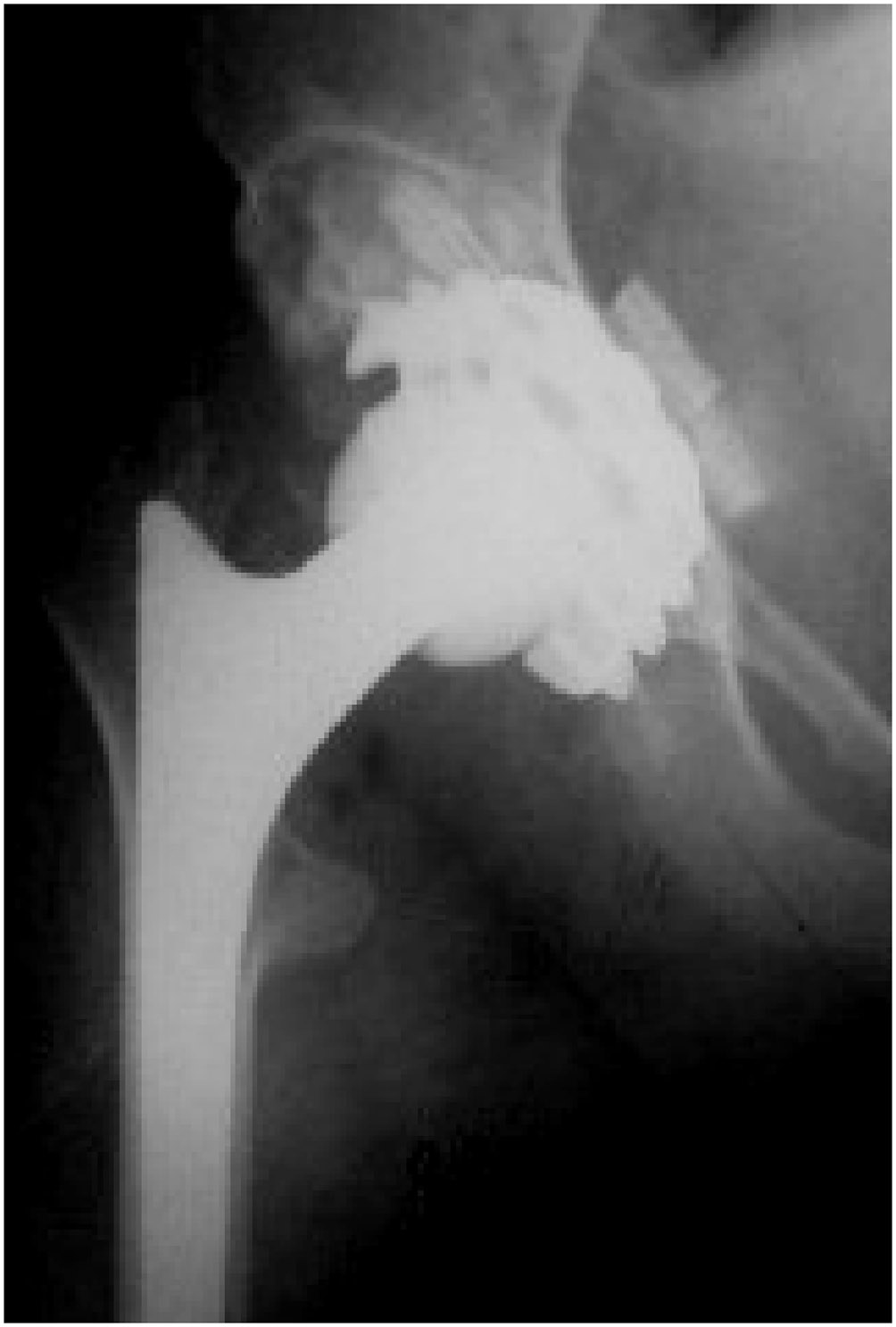
The specific case of a young patient of Professor Touzet at Necker Hospital required the development of the shape of the future Bicon cup. (6.7.1.Doc 1, p. 56, 58) This patient was approximately 18 years old, 1.30 m tall and weighing approximately 34 kg, and was absolutely unable to walk again without reconstruction surgery. For this patient, no femoral stem size was suitable. In my personal workshop, I reduced the smallest AlloClassic stem available to obtain a stem equivalent to size "minus 4" on the current SL Plus stem scale, with the added benefit of reduced taper to accommodate the femur, which had remained almost cylindrical due to the lack of stress.
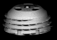
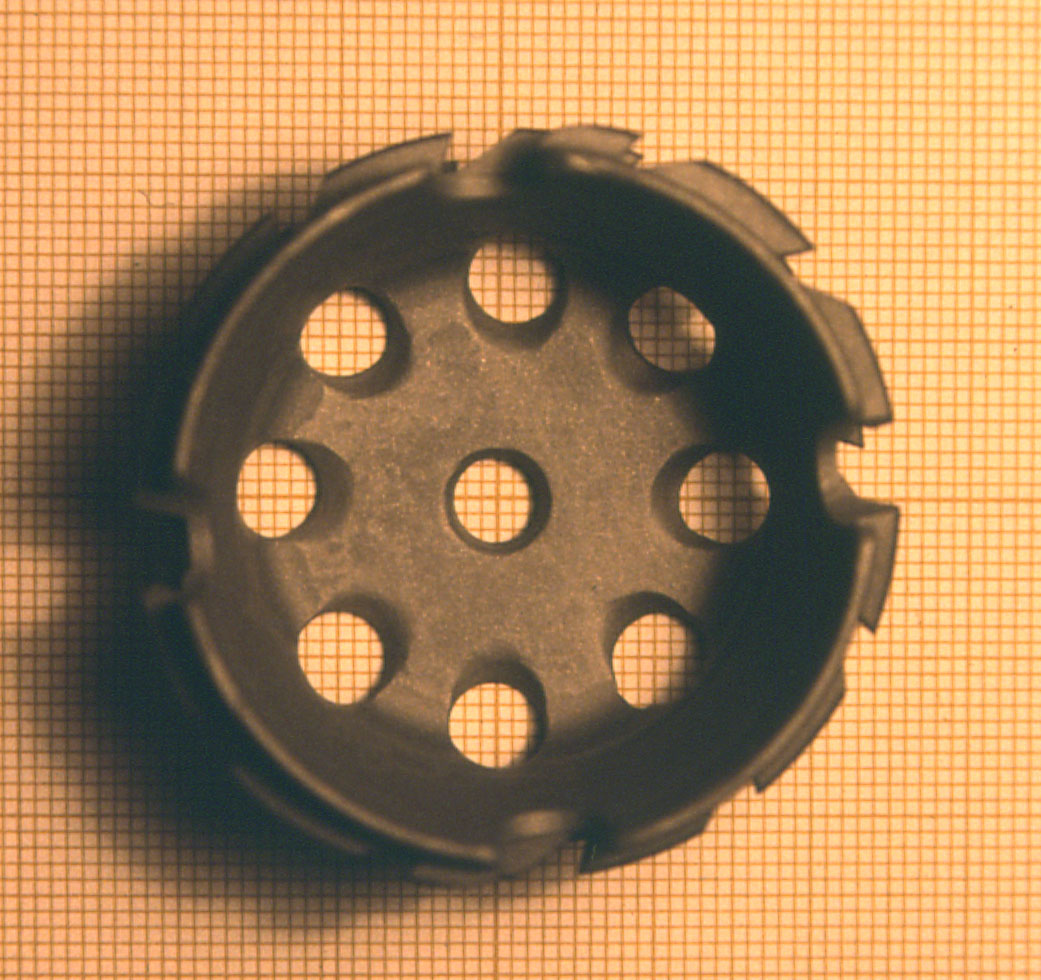
Regarding the acetabulum, the smallest size (called "52", but with an actual diameter of 42 mm) of the AlloPro monoconical shell was still too deep. The only way was to modify it to make it a little less bulky. To achieve this result, I had a wide, oblique chamfer milled around the frontal shoulder. The holes were intended to accommodate numerous bone implants.
For this unique case, I reground a corresponding acetabular burr into a Bicon shape to reduce the expected damage to the acetabulum.
The implantation went perfectly, and the outcome was excellent.

5.3.1.6. Adaptation to the elastic movements of the bassin
With the design of the cotyle Bicon More, my fundamental wish was to carry out an implant which accurately follows the small elastic strain of the bone of the basin and the area acétabulaire during the normal activity of a patient.
The natural deformations of the acétabulum are transmitted to the shell by the whole of the teeth encrusted in a tight way in the bone and by the principal cone of the shell in contact tightened with the acétabulum.
The elastic behavior in the basin of an assembled Bicon cup is obtained thanks to the transmission of the constraints coming from the basin and the shell to the polyethylene insert. the insert supports the Titanium shell elastically because the contact is strictly without play in all the points of the assembly Titanium-Polyethylene. It is about a true composite assembly.
In the AlloPro shells or other relatively thin shells not having a junction at large surface, only Titanium defines elasticity in the basin, the small deformations of the shell not being transmitted to the insert because there is a play between these two parts and the contact takes place only in some points.
Certain shells, of which the thickness exceeds 3 or 4 millimetres can be regarded as rigid compared to the deformations of the basin.
The bone of the basin in the course of deformation runs up against a rigid obstacle. This conflict always leads to the formation of a thin layer of conjunctive medium absorbing the movement due to the difference in elasticity of the bone and Titanium. In the long run, the cranial migration of the implant is inevitable.
5.3.1.7. Adaptation to the elastic movements of the pelvis
In this composite assembly, the elasticity of the three elements—Bone, Titanium, and Polyethylene—must remain consistent, and only microscopic movements should persist. From small to large sizes, the thickness of the titanium shells, and therefore their elasticity, varies regularly. This variation should not remain proportional to the variation in diameters, but should remain smaller than the latter to adequately accommodate the dispersion of acetabular cup sizes, which never correspond exactly to the height and weight of patients.
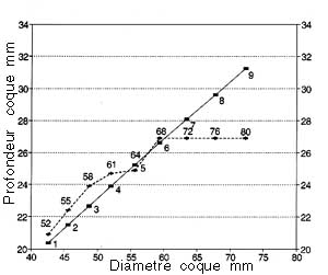
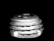
5.3.1.8. Shell Depth Variation with Size
Small shell sizes, intended for primary operations on small patients, have a relative depth close to a hemispherical shape. Larger sizes, intended either for tall patients or for patients whose acetabulum has been widened due to pathology or reoperation, are shallower.

The variation in depths compared to the shell diameters is very regular, unlike the AlloPro shells, which exhibit haphazard variations. This variation in the depths of the Bicon shells is obtained using the Growth Factor Method.
5.3.1.9. Anti-rotational stability of the insert in the shell
The first prototypes of standard inserts included four rectangular lugs. The four rectangular anti-rotation stabilization lugs were quickly abandoned, even before series production, because the anti-rotational stability of the Multicone Junction very quickly rendered any additional anti-rotational support unnecessary.
The stability of this multicone junction exceeded what I had imagined when designing it. Also, the elimination of the polyethylene lugs made it possible to continuously orient the insert through 360°, which is of great benefit for the precise orientation of future antiluxation inserts.
5.3.1.10. Advantages of the Single-Entry Thread
Unlike the 1986 AlloPro shells, which featured a double-entry thread (i.e., two coils wound around each other), the Bicon Plus shells feature a single-entry thread.
Thanks to this single thread, the Bicon Plus shell screws completely in about four turns with a moderate screwing force (half the force for the two-entry thread) and an excellent feeling of regularity, and always reaches the bottom of the preparation.
On the other hand, for the AlloPro cup, of the same size, with two threaded entries, a significant tightening force is required over less than two turns without always reaching the bottom of the preparation.
This comparison does not yet take into account the improved shape and reduced thickness of the Bicon Plus shell's teeth.
A good way to make this comparison is with a car's gearbox: the Bicon Plus cup is easily screwed in first gear, while the AlloPro cup is difficult to screw in second gear. It's hard to start a car in second gear without stalling the engine!
The high torque required to tighten a double-entry thread is such that most of the time, any tactile sensation of bone resistance, the arrival of the acetabulum at the bottom of the socket, or the locking, is lost. The force is so high that the operator sometimes risks exceeding the mechanical strength of the bone, "misty" the thread, and exceeding the possible number of turns, thus destroying the threaded structure created in the bone a few moments before. With the Bicon shell, the sensation of increased resistance at the end of tightening is clear, and the operator is in no danger of exceeding this resistance.
Furthermore, when the number of teeth in a single-turn thread, as in the Bicon Plus, is around fifty, the radius of each consecutive tooth increases only slightly, and the tip of each tooth will only detach about a tenth of a millimeter of bone. In contrast, with a two-turn thread, each turn is independent and has only about twenty-five teeth in total. The radius increase from one tooth to the next is doubled, the two chips to be cut simultaneously will be twice as large and resistant, and the tightening torque to be applied is quadrupled.
Regarding the depth reached during screwing, the AlloPro shell was often blocked before reaching the bottom of the prepared cavity. Windows at the bottom of the shell, first to observe the distance left empty and then to be able to fill it with bone chips, had to be created. (see detail below § 5.3.1.11.).
In the Bicon Plus shell, this defect has been significantly reduced by the biconical shape and the new tooth design, and the need to fill the gap between the shell and the bottom of the prepared cavity has become less frequent. When necessary, the three windows, which can be closed by a titanium rotary vane shutter, still allow the empty space to be filled.
5.3.1.11. TEETH
5.3.1.8.1. Grinding the teeth
This expression is used in the cutting and sharpening of saws, especially circular saws. In short, according to this principle, the back (the Heel) of a saw tooth must be set back from the sharp cutting edge of the tooth so as not to rub on the workpiece in contact.
In the old AlloPro Monoconic shell, the common outer contour of all teeth is a linear spiral at a constant distance from the conical main body. Therefore, from a mathematical point of view, the radius at the Leading Tip of each tooth is paradoxically smaller than the radius at the Heel of each tooth.
The radius increases linearly along each tooth, so the heel of each tooth slows rotation. This defect was later corrected at AlloPro.
From the design stage of the Bicon Plus shells, I included the bevel in the tooth contour design.
5.3.1.13. Tooth Flexibility
The tooth profile of the Bicon Plus shell stems from a number of considerations and experimental observations. The guiding principle behind the creation of this profile is primarily the pursuit of the ideal expressed by the term "isoelasticity," meaning an implant elasticity close to that of the bone, which would adapt to small deformations of the bone subjected to the constraints of walking.
From a microscopic point of view, each point of the implant facing the bone should have movements less than the size of a bone cell, or about thirty microns. (see § on Micromovements 2.10.2.)
The term "isoelastic" was introduced by Robert Mathys when he created his isoelastic stem. Unfortunately for this stem, the evaluation of isoelasticity was seriously erroneous. The stem ended up being hyperelastic, that is, much more flexible than the femur at the same location. (It had to be stiffened later with a screw towards the trochanter).
It is obvious that isoelasticity cannot be achieved by a mass-produced implant given the great variability of bone resistance not only by bone hardness but also by the individual structure of the cancellous bone which can be more or less dense or rarefied.
5.3.1.14. Thread pitch and number of teeth
In Bicon shells, between two consecutive turns, the thread pitch, defined by a Growth Factor, narrows slightly for small sizes and widens for large sizes. This results in a sufficient number of teeth for small sizes to allow for engagement in a bone structure that is statistically thinner than for large sizes.
Contrary to this, the hull monocone AlloPro with the same thread pitch and thickness of teeth for all sizes, small sizes of the shells could not receive a reduced number of turns and teeth. The distribution of hooking into a small acetabulum became random. \ \
5.3.1.15. Theory of the Secondary Function of Teeth
My theory attributes two completely independent, successive functions to the shell teeth. Once the shell's primary and obvious function has been fulfilled through efficient self-tapping with teeth whose shape has been optimized, easy screwing allowing the shell to reach the surface of the bone prepared by the bur, and the achievement of a conical junction between the main cones of the milled bone and the shell, thereby placing the bone under uniform prestressing over the entire junction, the teeth, their profile, their design, and their sharp points have definitively fulfilled their primary role.
In the secondary period, where all of the shell is closely in contact with the bone, including the surface of the fins, the screw-shaped fins does not have more any importance. What matters is the quality of contact on large area of the largest number of teeth, the nature of the microstructured surface of the teeth, and finally their elastic properties.
On the other hand, the profile of the teeth, the surface of the wing teeth, and their relative elasticity remain of great importance for the future.
The secondary role of the whole of the fins becomes a function of macroscopic replacement of old bone structure that was destroyed by the disease and milling.
In the Bicon shell, the fins act as a draft favoring the trabecular structure of cancellous bone reconstruction that existed in the vicinity of the cortical layer.
The thin titanium body of the shell acts as a cortical layer whose natural thickness was natural for one to two millimeters over the entire hemispherical surface of the acetabulum.
Bicon cup for this role of prosthetic bone structure appears soon after implantation due to the greater ability of this shell to enter into the prepared cavity and is closer than one millimeter in all the walls.
The Bicon cup does not require bone growth to ensure the primary stability. The primary stability is practically guaranteed at the end of the intervention.
I recall here what I call bone regrowth: reconstruction of the bone above the millimeter and needs several months to settle. All the previous cups, especially the cup AlloPro, required bone growth to fill the spaces not affected by the implant in his screwing and especially at the bottom of the cup.
This is an integration in bone cells, integration of the metal and the existence of living cells in contact with bone, microscopic and perhaps molecular with the metal surface. I chose this arbitrary millimeter barrier between the two variants because the millimeter is about the limit of what an X-ray observations can provide, below the millimeter between bone and the implant can not have visual certainty. In addition, artifacts can also cause radiological edgings that reinforce the limit of a millimeter in this discussion.
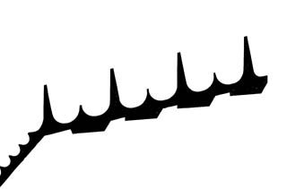
5.3.1.16. The tooth profile
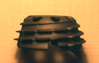
I was inspired to set the teeth of the Bicon cup, trumpet reversed profile of the Eiffel Tower, symbol of stability over time.
By analogy, the teeth of the shell has a relatively thin triangular section, the angle is a dozen degrees and rounded very large trumpet-shaped teeth meet the body of the shell to ensure their stability and progressive elasticity of the base to the tip. In the vicinity of the tip, the fins have a thickness of about 0.4 mm varying somewhat with the size of implants. This thickness is still sufficient to maintain some strength during handling but its smoothness makes it possible the wings to be encrusted in the cortical bone without causing transport of chips
Unfortunately as one will see it in another chapter, the metal which was selected has mechanical properties quite lower than metal than I would have wished at the time of the design, Titanium with Vanadium.
Indeed, with the unalloyed titanium, the tips of the teeth can deform when they encounter a Kirschner wire or a spacer, meeting with these instruments really was not planned in the design, not more than the meeting of a tree in the design of an automobile.
If necessary change of orientation of the shell, I recommend to unscrew completely to avoid forcing the tip of the teeth that have begun to sink into the bone. Teeth practically not removing bone, there is no risk to start screwing after a change of direction.
The rounded arc at the base of the teeth with the body of the implant play an important role in promoting the vitality of bone at the bottom of the interval between two turns of teeth.
Indeed, if the teeth were connected at right angles to the back of the intervall, the bone cells would not be irrigated, live and active. I refer to the study that I prepared in 1999 for a presentation in Vienna in which I defined the concept of a "solid angle" minimum below which living cells at the bottom of a cavity-shaped crater can not develop. This solid angle can be evaluated at least one cone about 6O degrees of opening.
On the shells AlloPro, osteointegration could not take place until the base of the teeth precisely because their contact angle, without transition curve at the base, was acute (75 °).
Regardless of research strength, the desire to extend the Bone vitality to the base of the teeth has confirmed to me in choosing relatively large rounded at the base of the teeth and make them vary, depending on size, with an independent Growth Factor.
5.3.1.17. The angle of the teeth with the main cone of the shell
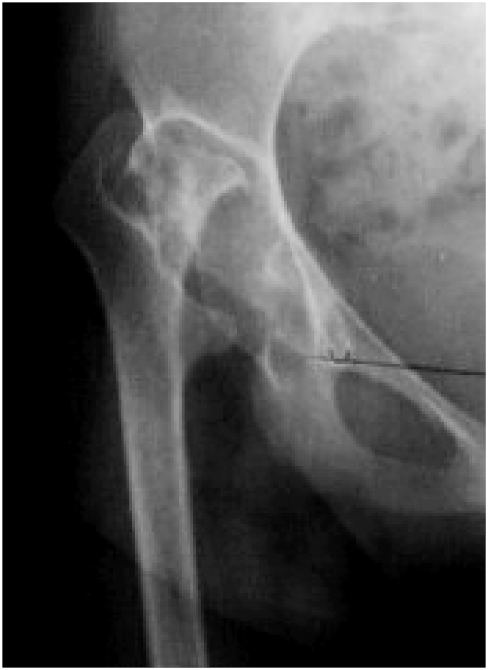
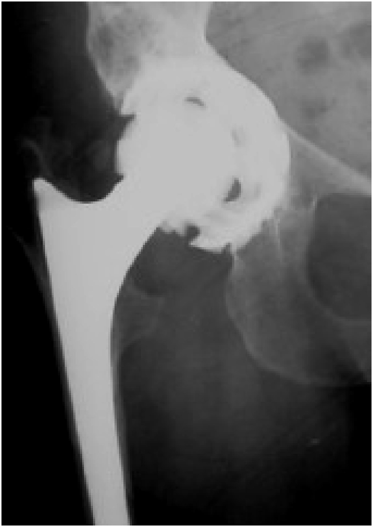
On radiographs of knees or hips, I clearly observed that the bone trabeculae end in the direction perpendicular to the cortical surface of the cortex. These spans reinforce the resistance of these relatively thin corticals, 1 to 2 millimeters thick supporting them as the pillars, and distribute the stresses in the underlying cancellous bone.
Unlike the monocone AlloPro shell which the acute angle between the teeth is only 75 °, the backface of the teeth of the Bicon shell is inclined 87 ° to the surface of the main cone the shell, which makes teeth almost perpendicular. This provision, supplemented by the flare, remove the not osseointegrable acute angle, of the monoconical AlloPro shells.
This arrangement, visible on radiographs, to suggest to some that the teeth had been distorted during implantation.
This also corresponds to my observation of many X-rays: in the trabecular structures supporting the sliding surfaces as in the knee or hip, the bone trabeculae obviously lead perpendicular to the cortex. This corresponds to the secondary role of draft trabecular structure.
5.3.1.18. Thickness and size of teeth defined by growth factors
Changes in the teeth of the shell Bicon plus in thickness, in length, distance and thread pitch is regulated by several Growth Factors independent of the size of the implant. They are not proportional to the size of the implant.
In comparison, in the monoconical cups AlloPro all the teeth of the smaller 52 to the very large 72 had a constant depth of 5 mm, uniform thickness, a constant distance between the coils. For all sizes and thread pitch of the teeth were unchanged, resulting in an angle between the coils and the axis of the shell an excessive and uncontrolled variation.
To keep the teeth, while leaving them looking for a finesse of flexibility, a sufficient mechanical strength for handling during implantation does not damage, I applied growth factors independent of each other. This variation was more moderate than the variation in diameter. If the variation of the thickness of the teeth remained proportional to the diameter of the shells, teeth of very small size would not have kept adequate strength, and the teeth of the larger sizes were not sufficiently elastic.
5.3.1.19. The clearance between the insert and the prosthetic head
As is normal for all the cups, the diameter of the spherical cavity is slightly larger than the nominal diameter of the head. The diameter of the ceramic heads corresponding to the nominal diameter, 28,000 mm, for example, with a margin of a few microns. This accuracy is far from being achieved with polyethylene inserts. The inner diameter of the polyethylene hemisphere 28.8 mm leaves a set of 0.4 mm around the head.
This clearance will prevent the tightening of the head by the insert in the manner of a disc brake at the moment when the compressive load of the head in the acetabulum is greatest and where, after transmission of the elastic deformation of the basin, all composite thin shell of titanium and polyethylene insert deforms and squeezes.
In the case of a pair of sliding metal-metal, the clearance between the metal head and the sliding seat to be much lower. The sliding seat retains some flexibility in sandwich mounting and the clearance should be sufficient to avoid a too intense friction and the braking effect.
In the case of a pair of sliding ceramic-ceramic, we can consider that the seat slip ceramic is virtually rigid, the definition of residual clearance is the manufacturer of the two common components of the couple.
5.3.1.20. Exceeding the insert from the metal shell
All inserts Bicon after impaction, must exceed by about a millimeter of the metal shell. According to the Operator, the impact forces are variable and final exceeding can not be constant. A small variation is predictable due to dimensional tolerances in the production of the two components. I have excluded an additional edge to cover the thickness of the edge of the shell as it might exceptionally prevent impaction of the Multicon Junction. To guarantee this slight overshoot in the design of inserts antiluxation polyethylene or metal-metal, it was necessary to slightly release the center of the spherical head to give the movement of the neck range of motion possible.
5.3.1.21. History of the windows in the monoconic shell AlloPro Zweymüller
Having realized several times during the operating assistance, the monoconic shell AlloPro still did not reach the bottom of the acetabulum, I proposed in 1987 at AlloPro to drill four holes in the circular disc in front this shell.
The original idea was the need to control the remaining distance between the bottom of the milled preparation of the acetabulum and the disc front of the shell. These holes also made it possible to control the inclination of the shell from the initial milling, and insert a few small pieces of bone. The amendment was rejected.
I experienced the benefit of holes for the control of the bottom and filling with bone fragments or bone substitute in connection with a real case of Professor Touzet.
Yet two years later, two bean-shaped windows were performed at the bottom of the monoconic AlloPro shell. A diagonal bar stand mounting thread screw on the instrument. The frequent need to fill the space remaining front had become obvious. The two windows at the bottom of the shell and the diagonal bar supporting the mounting thread has been the subject of a patent filed by Sulzer.
In this area of the shell, the fear of direct contact between the polyethylene and the bone was justified, due to severe disappointments in the medium term of the Endler cup in polyethylene. The elimination of direct contact with the bone of polyethylene has been solved by superimposing a sheet of titanium disk on the front of the polyethylene insert.
I had observed in the monoconic shells AlloPro that bone fragments placed through the windows stood out during the implantation of the insert and therefore the insert snaps not correctly. We had to remove the insert, replace and reposition the fragments of the insert.
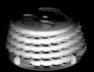
5.3.1.22. Windows of the hull Bicon Plus
I wanted, at the beginning of the design of the cup Bicon Plus, to find alternative solutions and if possible better.
Since two windows and a transverse bar were patented, I decided to bore three windows in circular form of sector, of approximately 60 degrees. So that polyethylene is not in contact with the bone and that possible fragments of bone of filling cannot arise by the three windows at the time of the impaction of the insert, I imagined a rotary Titanium closing fixed inside the bottom of the cup. This system of obturation made up of three circular sectors recovers simultaneously the three windows after a small rotation.
5.3.1.23. The closing of the windows under tension, without play and remains of usure
Of my experiment by Carl Zeiss, I knew that any mobile assembly was to be without play. I thus stabilized this system of obturation of the windows by a spring effect. To obtain this spring effect, I drew the bottom of the slightly conical cup so that the sectors of obturation are deformed and permanent energized. The Titanium blade of the rotary shutter is fixed by a relatively firm riveting on the bottom of the cup. This system of obturation with sectors is described in the patent containing the innovations which I brought to the cup Bicon Plus, consultable in appendix 9.8.4. This patent is property of the Group Smith and Nephew.
5.3.1.24. Choice of the metal of the cup
Right from the start, I had designed the cup Bicon Plus of alloy of Titanium and Vanadium, TA6V, this alloy having great mechanical qualities as its broad use in aeronautics shows it.
The first monoconic screwed cup AlloPro was produced out of pure and nonallied Titanium, but the poor mechanical properties of this nonallied Titanium did not give place to problems because the cup was still rather thick.
It is only on the cup Bicon, thinner, than the relative brittleness of nonallied Titanium had as consequences some peripheral cracks and some deformed or broken teeth.
The first series of cups Bicon Plus were manufactured by turning and milling starting from cylindrical Titanium bars. Thereafter, for a question of saving of Titanium and time-saver in production, the cups manufactured in great series were machined starting from outlines in the shape of Titanium cups obtained by forging. Paradoxically, forging did not bring to Titanium cups the advantageous mechanical properties which it usually brings to Titanium stems of prostheses.
The forging of the cups directed the crystalline structure of metal in radial direction, therefore in an orientation perpendicular to the equatorial constraints of extension which the cups could receive in certain extreme cases. In some cases, inserts still badly directed at the time of impaction, caused radial cracks. I am persuaded that the cup-holders were responsible of this.
The cracks observed could also have like starting point the corners of the crenels of screwing too perfectly rectangular and without any round-off. The origin of this form will be explained low.
The choice of the metal of the cups Bicon Plus was made by the Producer, probably for reasons of marketing and similarity with the AlloPro cups, on nonrather allied Titanium than on an alloy of Titanium to Vanadium or Niobium, mechanically more resistant.
Some teeth, whose metal was fragile, broke by the meeting with a spacer or a pin, releasing the acétabulum, planted a little too near.
5.3.1.25. Screwing Crenels
I approve the recent removal of the screwing crenels insofar as a reliable instrumentation is available. A continuous periphery of the instrument carrying the cups is necessary to preserve the circularity of the cup and to rigidify it during screwing.
For the many users who did implant cups with screwing crenels,I make a point of recalling the history and specifying the constraints which were imposed to me by the Producer.
5.3.1.26. History of the instrumentation
For the establishment of the cups Bicon Plus, it was obligatory to be able to use at the beginning the instrumentation of the monoconic cups AlloPro already largely established in 1993, after a possible minimal adaptation. There was no question of basically changing the mode of usual screwing of the cups.
The keys of the monoconic cups AlloPro comprised 4 cylindrical “ears” which clung in the 4 cavities, in the form of half rings, with the periphery of the cup. This form was the direct consequence of the 4 “ears” of antirotatory stabilization of the polyethylene inserts. These 4 cylindrical ears were the subject of a patent.
I thus had to seek, for the cup Bicon Plus, one different form, concretized by rectangular crenels, and consequently of the keys comprising of the also rectangular nozzles.
5.3.1.27. Design of the keys for cups Bicon Plus
As of the design of the Bicon Plus cups, knowing that I wanted to make them relatively flexible and thin, the keys for cups were obligatorily to exclude any deformation from the cups during the process of screwing and autotapping. To obtain this rigidification and to prevent the permanent deformation of the bottom of the cup, I defined a central cylinder on the keys practically coming in contact with the central disc from the cup.
A space of approximately 100 microns was to be held between the nose of the key and the frontal disc to allow a temporary elastic strain of the bottom of the cup and to put the cup under prestress until the end of screwing.
This rigidification was obtained during the powering of the frontal disc of the cup by the last half-turn of the fastening screw on the key.
The keys for Bicon Plus cups were produced nevertheless without complete circular range.
During screwing, the cup is subjected to significant efforts and osseous resistance met all around the acetabulum is far from being uniform. \ \ The cup not rigidified on its periphery could be ovalized and the operator did not realize from there that at the time of the positioning of the insert which had an unexpected resistance.
This defect was corrected, most of the time, by a more violent impaction which could involve a crack of the cup.
I approve the suppression of this system of keys with cotyles (9.7.1.Doc4, p91, fig12). I hope however that the new system without crenels ensures as I wished it in the beginning, the temporary rigidification of the cup during screwing.
The threaded rod fixing the AlloPro cup on the corresponding key was perfect as long as the frontal disc of the hulls did not have windows yet. When the frontal disc was bored by the two windows, the threaded rod, tightened a little vigorously, drew and deformed the central bar. This deformed central bar prevented sometimes the correct insertion of the insert.
5.3.1.28. Drills for cups
The drills for the monoconic cups AlloPro, with relatively aggressive frontal edges and frequently perforating the bottom of the acetabulum were to also be usable for the Bicon cups at the beginning of their marketing.
In fact, the manufacture of biconical drills quickly proved necessary because the spreading out of the sizes of the monoconic cups AlloPro and the cups Bicon Plus, spread out by the method of the Optimized Sizes and calculated with Growth factors, differed notably for certain sizes.
5.3.1.29. Dimensions of the screwing crenels
The rectangular shape of the screwing crenels being established, a requirement of production involved the need of constant size of the crenels for the nine sizes of cups. Indeed, the centering of the outlines on certain automats of the production was obtained by a cross made up of 4 bars of rectangular section, commune with all the sizes. I had to give up the crenels of regularly spread out size, whose dimensions and depths were already calculated by the Growth factors.
5.3.1.30. Reasons of the 8 peripheral crenels of the cup
As I exposed, the general line of the cup Bicon Plus was to be relatively thin and flexible.
To improve the flexibility, I had envisaged 8 crenels of different depth according to the sizes. In addition, I knew already that tilted inserts antiluxation would be essential in the years to come and that they would require stable orientations that the 8 crenels, each one directed with 45°, would allow.
Unfortunately, for reasons of manufacture, these crenels found of constant size thereafter. That had as a consequence of the too large crenels for sizes 1,2, 3 and 4.
5.3.1.31. Insertion of the insert manually or with an instrument?
The fixing of the inserts in the cup takes place by the Multicone Junction. Just as with a simple conical junction, the centering and the orientation of the insert are carried out naturally safe if this natural orientation is opposed by the insert holder. Indeed, the long rigid handles of the insert holders prevent the Operator from feeling the natural tendency of the insert to be correctly directed in the cup. It even arrives that of the Operators start to impact the insert still assembled on the inserts holders without to have felt that the orientation is not yet perfect.
It is to avoid this risk which I advise to always begin with the manual installation of the insert by small movements of orientation and rotation. Thus, the feeling of the good orientation becomes obvious and the phase of impaction can be started.
5.3.1.32. Impaction of the insert with a spherical instrument
It is imperative to impact the polyethylene inserts in the Bicon hull with a spherical instrument without edge. The support must take place at the bottom of hemispherical surface to make it possible the insert to slightly tighten itself following the powering of the Multicone Junction. Also, the spherical impactor without edge is not likely to influence in a bad direction and in a dissymmetrical way the natural orientation of the insert.
5.3.1.33. Possible extraction of the insert
The need for extracting an insert fixed by a Multicone Junction is exceptional. Not to compromise final solidity and the reliability of the junction, I did not want to make the inserts too easily extractable. For approximately three cases out of thousand, the 997 others would have been penalized.
In the event of peremptory necessity for extraction, it is possible to bore two or three holes in polyethylene until the meeting with titanium and to screw there cortical screws after tapping which make it possible to raise the insert carefully by tightening the screws alternatively.
----
Next implant: